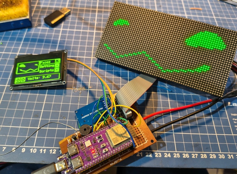
DIY Route!
Ok, so you don’t have a way to buy an assembled protopanda or just wanna build your own for yourself. I get it. As they said in the 2005 movie “Robots”: “Oh honey I’m so sorry you missed the delivery. But that’s okay, making the baby is the fun part.”
Let’s do it!
Important information
This project is still a work in progress and very little amount of people have done the DIY route so far. It’s possible and you can totally do it! But it won’t be as good as a protopanda assembled from the provided PCB.
This guide will require that you know a little of soldering and the basics of using a multimeter (measuring voltage, resistance and continuity). There are guides on the internet teaching those, so this won’t be taught here.
Some parts can be replaced for others, like the resistors, don’t need
to be specifically a 3k and a 10k, you can use like a 30k and 100k. I
tested even with a 5k/15k. If you know what a resistor divider is, the
proportion should be around 1/3. The MCU can’t be replaced. IT NEEDS TO
BE ESP32 N16R8
You’re dealing with ESP32, this microcontroller uses 3.3v, so if you accidentally wire or leave a solder bridge between the 9v or the 5v and any of its GPIOs, say goodbye to your ESP.
Some buck converters have issues with extra capacitors, so the 1000~4700uF capacitor needed further in the guide might be unnecessary.
Parts needed
- One of the 5v 3A buck converters: option 1 / option 2 / option 3
- PD trigger: Option 1 / option 2
- SD Card module
- OLED screen
- ESP32 N16R8 dev board
- Buzzer 5 or 3.3v
- Connector for the HUB75 (Get the 16 pin one)
- WS2812b LED strip
- 40x10mm 5v fan
- Some female pin headers
- Some resistors (1k, 3k and 10k)
- An electrolytic capacitor between 1000uF to 4700uF at least 6.3v
- Any push button
- A perf board
- Some wires
- An SD card (try getting the smallest one you can find, like 2gb~8gb)
- 2x P2.5 HUB75 panel
- HUB75 power cable (usually comes with the HUB75 panel when you buy it)
- 2x HUB75 data cable (usually comes with the HUB75 panel when you buy it)
Optionals for external use:
Tools
- Solder
- Soldering iron
- Cutting pliers
- A support for the PCB. Some call it third hand.
- Multimeter
- Some wires
Yes, you’ll be soldering stuff here. I don’t recommend you use jumper cables. They will get the job done yes, but they come loose easily and that WILL happen a lot and you will go crazy.
Naming conventions
There are a few naming conventions that can be confusing, so to help with that you can use this guide to help during assembly.
- VCC - Means ‘Voltage at the Common Collector’. Usually where you’re going to provide power or where power is being outputted. In the schematic this usually means 9V, 5v or 3.3v depending on where it’s pointed. In simple terms it’s the positive terminal.
- GND - Means ground. In simple terms it’s the negative terminal. It’s normal for it to be shared amongst the elements.
- SLC/SCK - Serial clock, the clock pin of the I2C bus. Sometimes it’s written as SLC other times as SCK. They’re the same.
- SDA - Serial Data, the data pin of the I2C bus.
- GPIO / IO - When saying IO5, GPIO5 that means the same thing.
Assembling
My idea with this guide is to provide a step-by-step guide until you have something finished. Each step we’re going to check if we did things correctly before going forward. It might look complicated at first but worry not my friend!
Gathering parts
With all the tools and parts, let’s go!
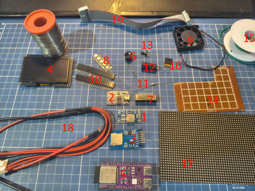
Here’s what we’re going to build.
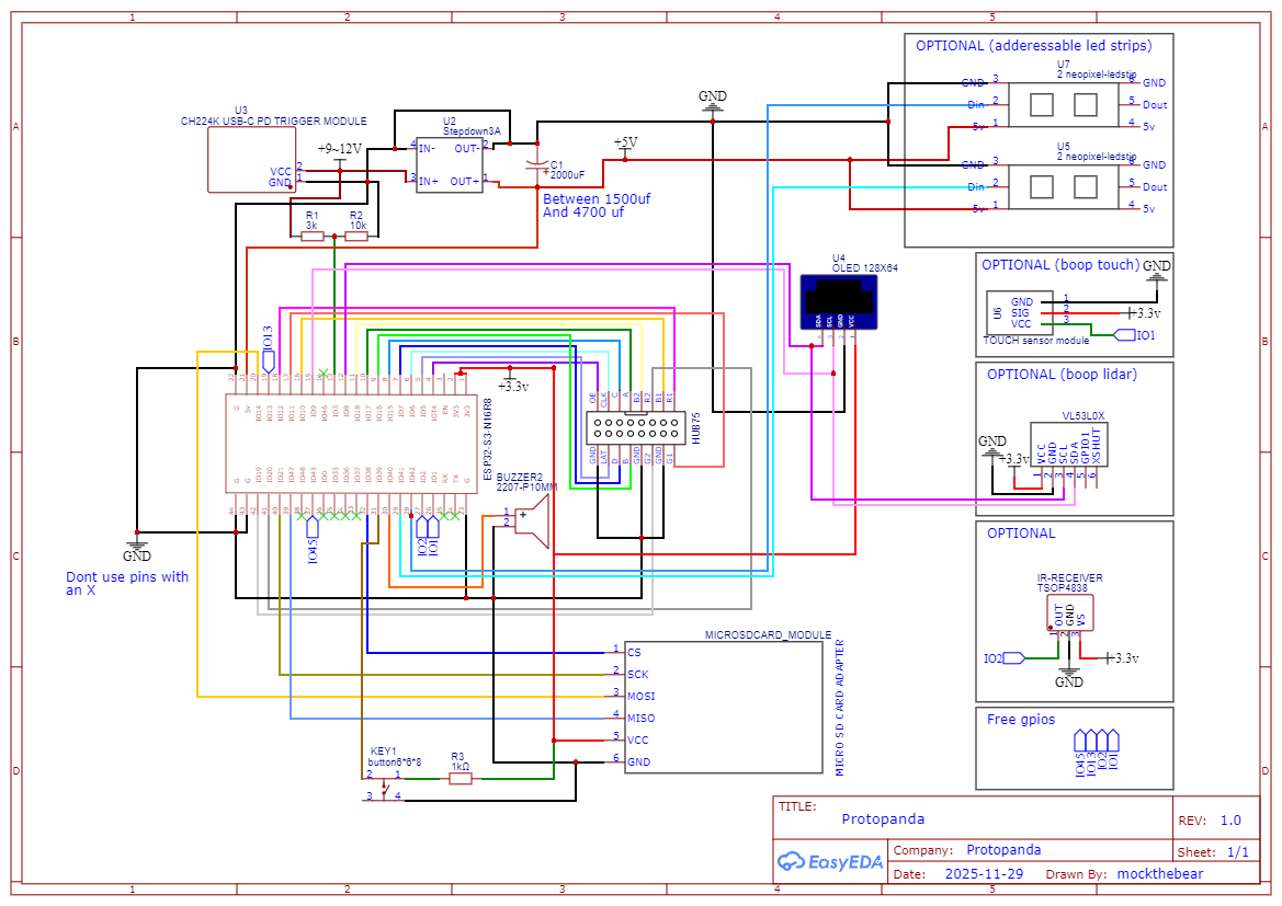
IMPORTANT: In the schematic, you see
IO9,IO10,IO33(inner number)… As you can seeGPIO9/IO9is on pin 15 at the schematic (outer number). In this guide, when we say: “connect something to IO15, that means to connect on GPIO15 that is in the 8. Not connect in to 15 that is IO9. USE THE NUMBERS INSIDE THE SQUARE, NOT THE NUMBERS OUTSIDE
Power
IMPORTANT: Any wires used in the 5V or the 9V rail should be thicker. Get like AWG 20 or something bigger. If you solder the capacitor and the 5V stops showing, that means the module has a faulty over current protection, you might be fine without it. So if that happens, just remove the capacitor!
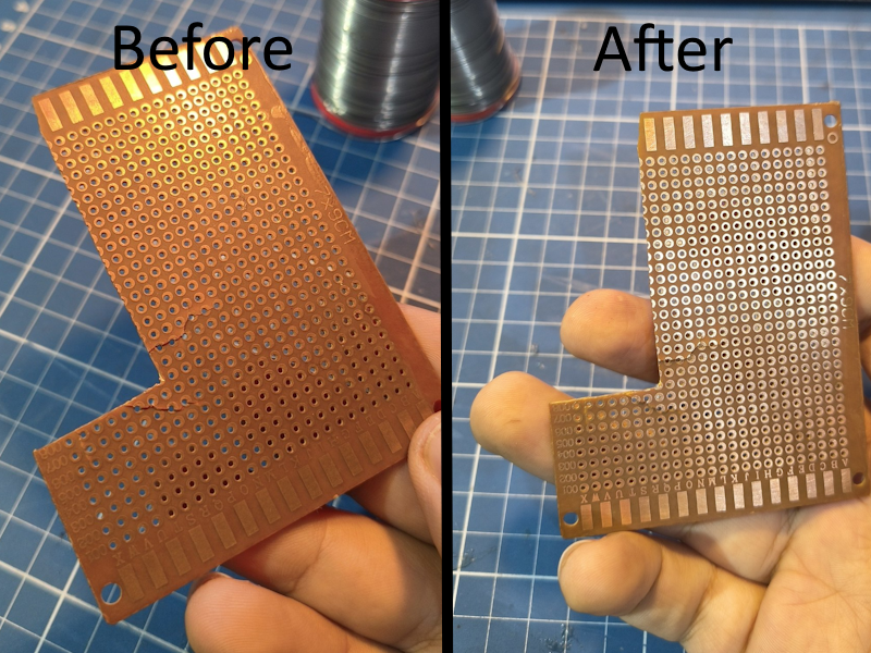
First, make sure to use some abrasive tool, like steel straw or a fine sandpaper to clean the perf board copper side. Copper oxides really really fast, and that oxide layer prevents solder from sticking on the board surface.
With that, let’s build this part on this section:
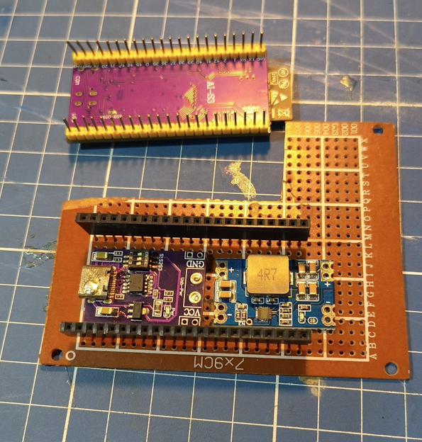
First of all, let’s position the components in the PCB in a way that it stays compact.
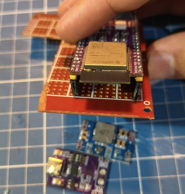
The idea is to use those female jumper headers to hold the ESP32S3 module in a way we can remove it if necessary. Also double purpose of lifting it a bit so we can place stuff under it!
So place the jumper headers in the ESP pins, and place it on the PCB leaving at least one row of space from the edge.
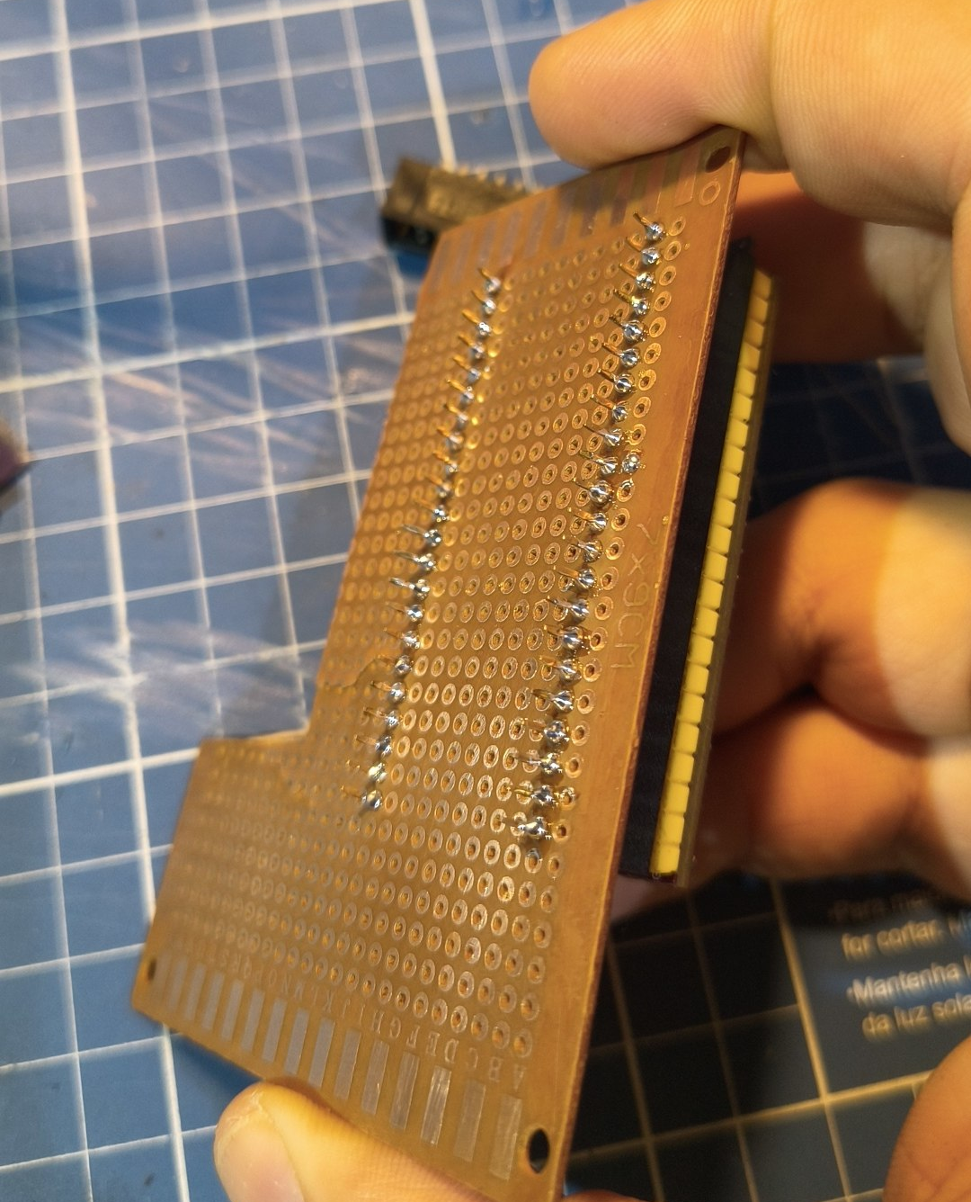
Now solder every pin and remove the ESP module from the pins.
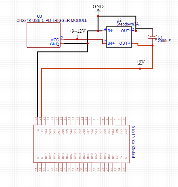
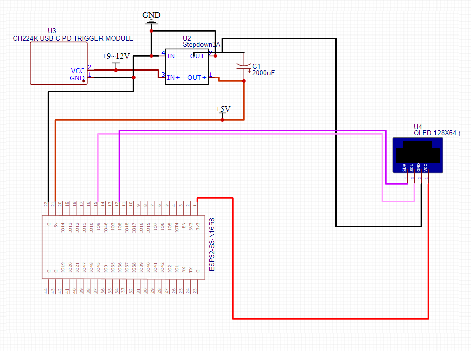
Now it’s time to wire the modules. If you’re starting, this diagram might help to indicate where to wire where.
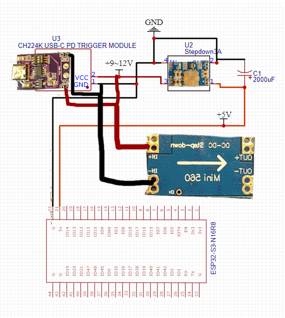
In short, there are two labels in the PD trigger module, VCC and GND. VCC means positive 9V and GND means negative or ground. Under the DC converter there are the labels indicating the polarity and where is input/output.
Make sure you’re not soldering GND to IN+ neither VCC to IN-. Also put two 2x female pin headers in the PD trigger and other 2x female pin headers at the output of the DC converter like this:
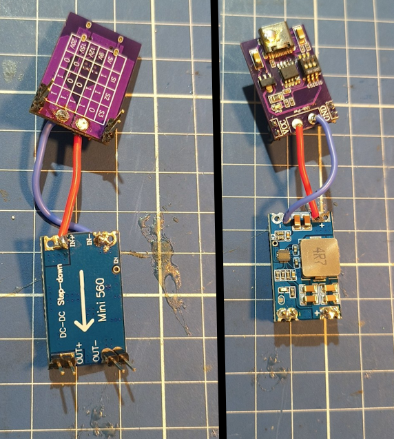
Place them at the board like this. Push them down as far as they go.
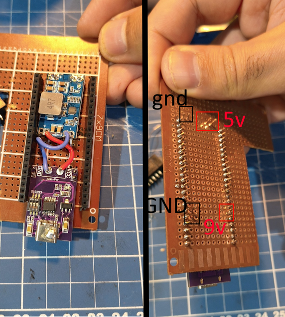
And of course, solder the pins on the other side.
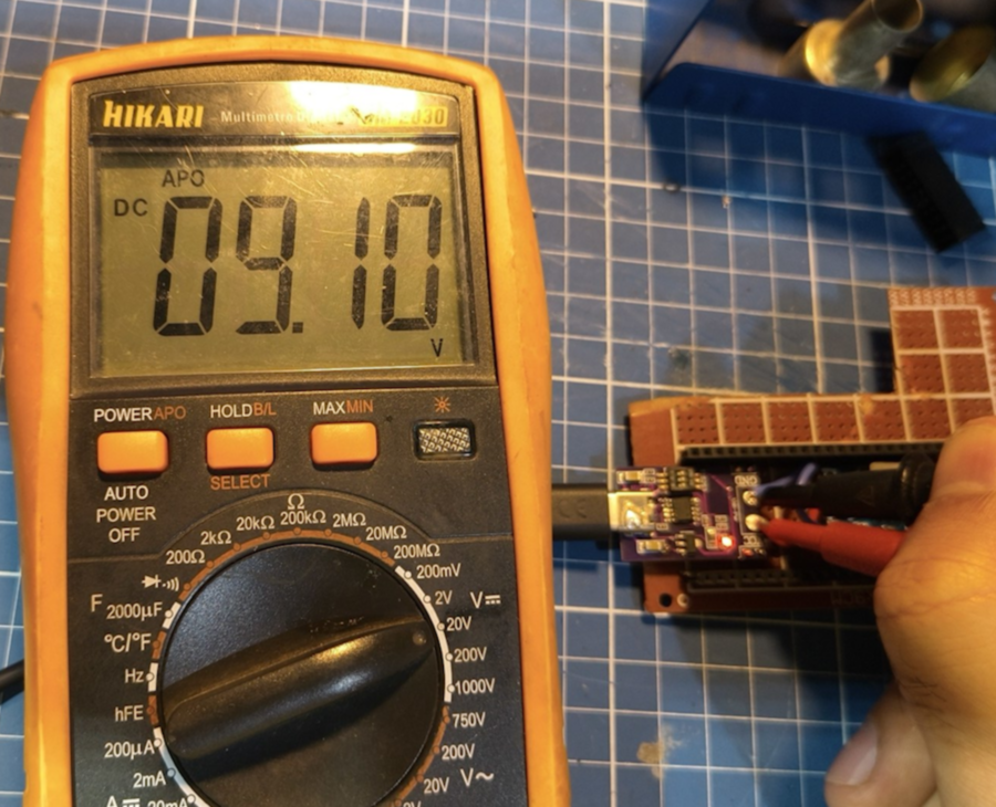
Now plug it in a power bank that has fast charge/power delivery, grab a voltmeter and put the probes (BE CAREFUL TO NOT SHORT THEM). If it shows 5V, you might need to adjust those switches.
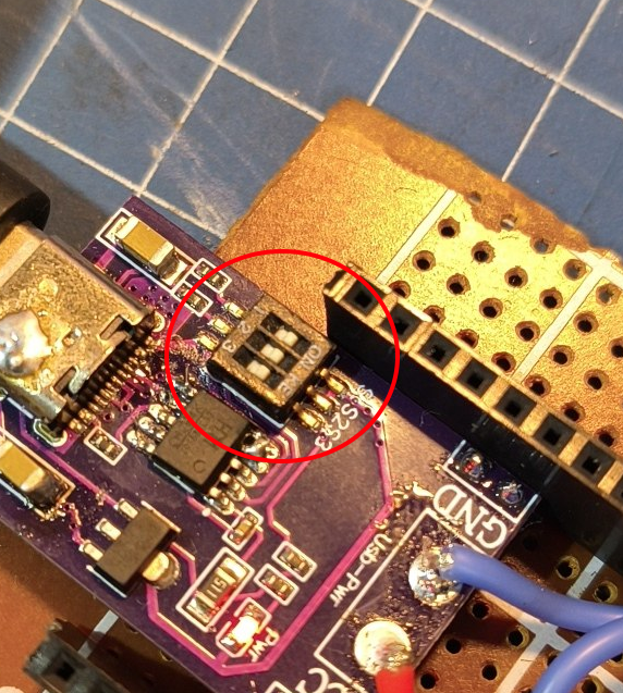
Adjust them until it shows 8.70v~9.10v.
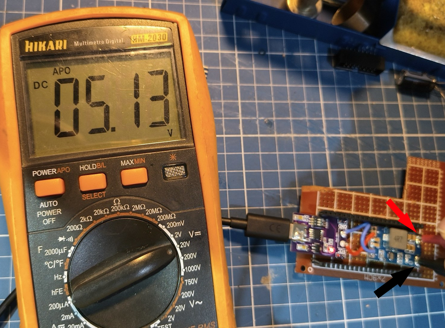
Now check the output of the DC converter. It should say between 4.9~5.2v.
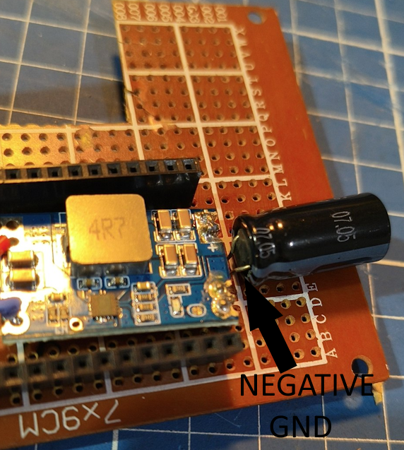
Once this is done, let’s solder the capacitor. First, carefully look on the capacitor, there is a usually white band. That indicates where the negative pole is. Place it in the board with the polarity in the correct way!!!! This is important. DO NOT PLACE THE CAPACITOR BACKWARDS
If you solder the capacitor and the 5V stops showing, that means the module has a faulty over current protection, you might be fine without it. So if that happens, just remove the capacitor!
On the other side you can bend the legs to work as a wire. Just cut the excess once you finish.
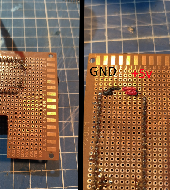
It is also okay to solder bridge the two pins of each side of the DC converter like the photo above. Place the ESP32 on the pin headers, and check if those highlighted pins match the photo. You’ll need to connect them accordingly. You only need one GND, but it’s a good idea to connect both of them if you’re patient.
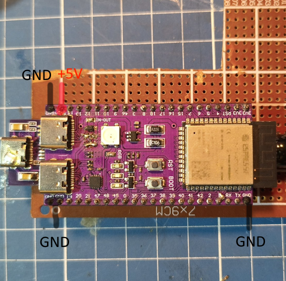
Be careful when you flip the board, because looking right now, the 5V is the second pin at the top. But looking from the bottom, that inverts, it’s the second pin at the bottom.
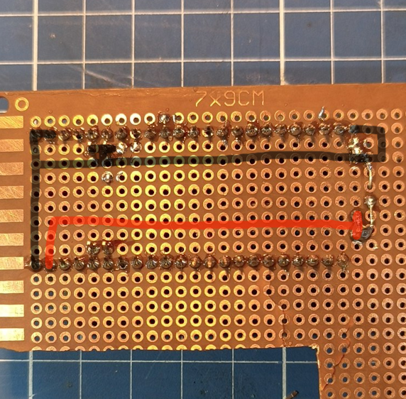
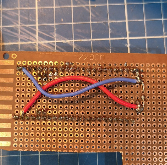
Now placing the ESP32 and powering it should light up!
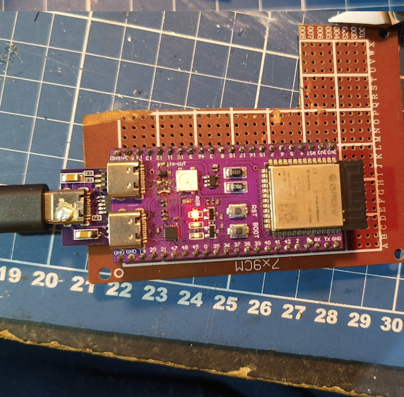
Done!
I2C
For this and all the other steps, first you need to flash the firmware. Use this guide for it.
Once you’ve flashed the firmware, let’s plug it in the OLED screen.
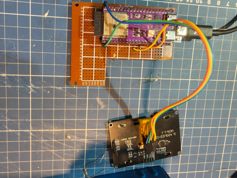
For this specific guide, I’ll be using a different screen, a bigger one so it’s easier to take photos of it. Remember when I said “No jumper cables!!”. Yeah, I’ll be using them but they will be soldered. The only reason I’m using them right now is because I can plug/unplug them from the OLED screen. See all this hardware on the guide will be repurposed later.
Just make sure SLC/SCK is going on pin IO9 and SDA is on IO8. GND is on any GND pin and VCC is at the 3.3v pin on the ESP. Double and triple check if you connected the wire in the correct pin!
Use some wires to join the PCB and the screen. That screen will go inside the protogen front frame, so you’ll need it to have these extension wires.
If everything is correct, when you power up, it should show an image on the screen:
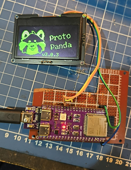
Then you’ll see an error popping up saying: “No SD card”
If you don’t see anything, check if you wired everything correctly. Check with the multimeter if there is 3.3v coming. If necessary use the continuity tester on the multimeter to confirm if the pin is correct.
Board optionals
Now we’ll install the internal button, buzzer and the resistor divider! Note that all of those can be skipped.
- If you don’t want the buzzer, edit the
config_defaults.hppcommenting this line:USE_BUZZER - If you don’t want the internal button to enable wifi on boot, edit
the
config_defaults.hppcommenting this line:ENABLE_EDIT_MODE - If you don’t want the resistor divider (recommended if you’re not
gonna use the PD trigger but a battery)
config_defaults.hppcommenting this line:USE_PIN_BATTERY_IN
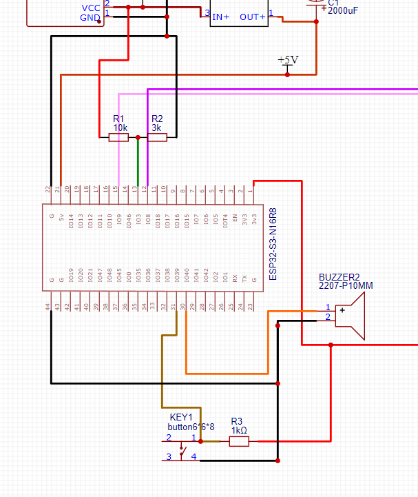
I’ll be placing the button and the buzzer near each other on that corner, but honestly, if you think there is a better place, put them there.
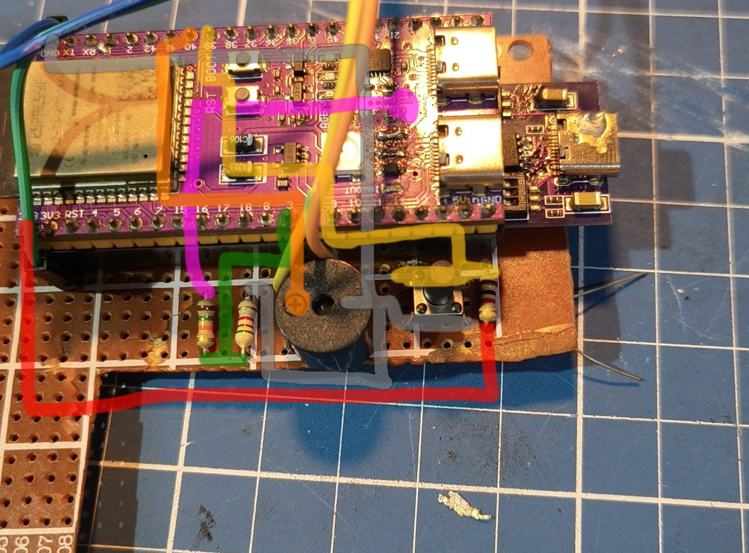
It’s a bit of stuff, but go slowly, part by part. For this part you can use any wire. You can go with thin wires no problem.
Internal button
Check how a push button works first. If they have 4 pins, that means two are in common like in this image:
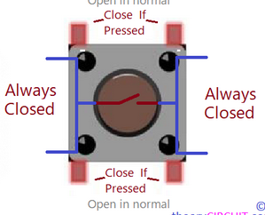
With that in mind this is how you wire it:
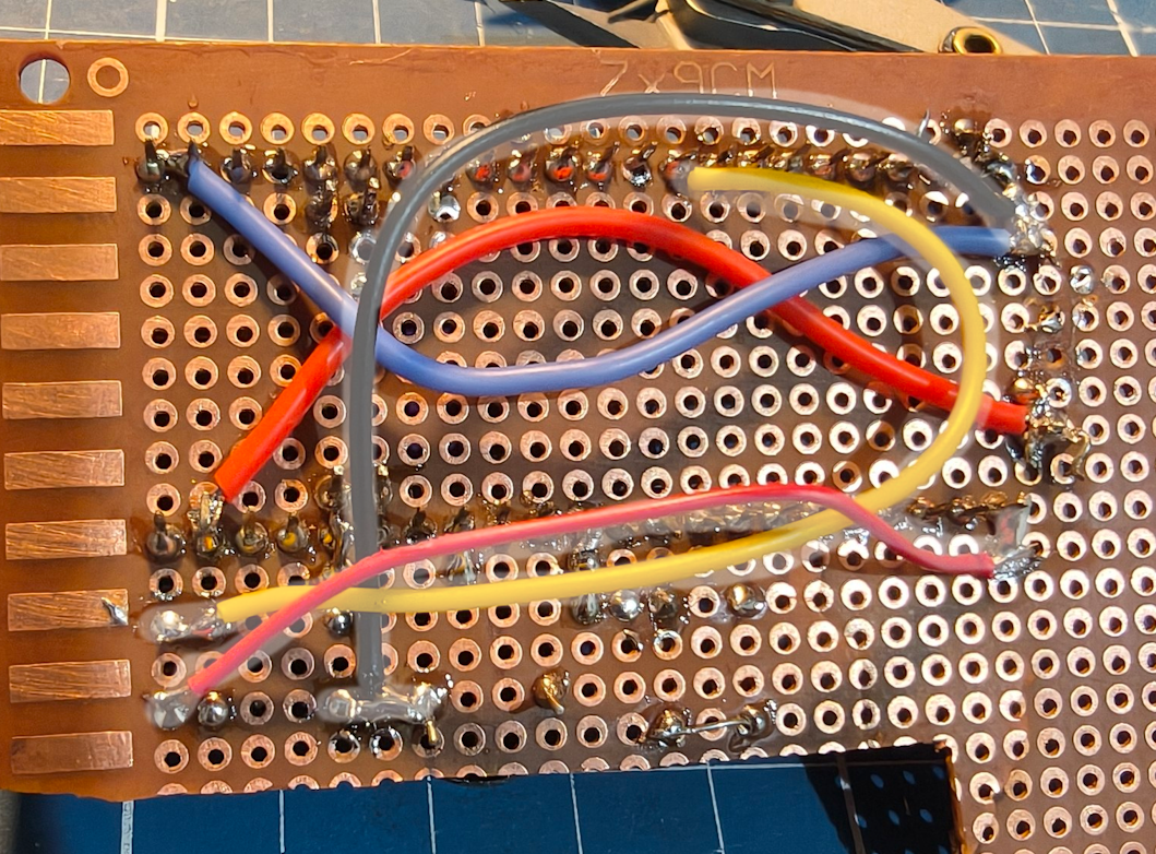
- The 1k resistor is connected to the 3.3V pin.
- The other pin of the resistor is connected to the button pin AND pin IO39 in ESP32
- The other pin of the button is connected to GND
Resistor divider
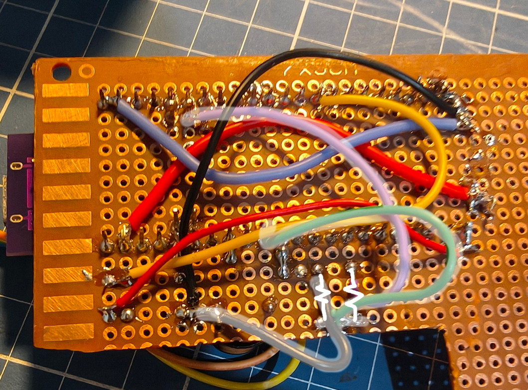
- The 10k resistor is wired between pin IO3 and 9V (that 9v pin header we put in the PD trigger)
- The 3k resistor is wired between GND and IO3
Buzzer
- The buzzer is wired between pin IO40 and GND. Check the marking of a + in the buzzer. That’s where the IO40 goes.
SD Card
Some SD card modules can be bigger or smaller… I’m using a big one on the tutorial but get one that fits for you!
I choose to place the SD card module there because that was the shape of my board. No need to put it specifically there.
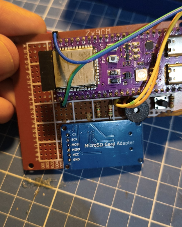
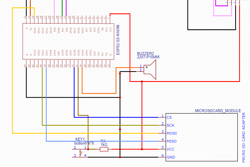
This is how you should wire it:
And when completed:
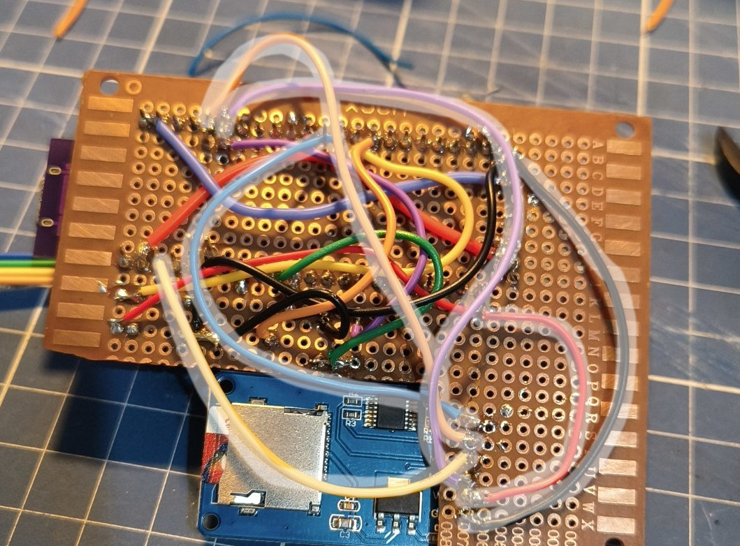
Now after you double check, put the SD card (make sure you put all
the required files in the SD card as it says in the flashing
guide). Powering on it should detect the card. If it does not, check
if you did the configuration part of the SD
card for the DIY mode. That means, changing the
PANDA_SD_MODE to 1 and reduce clock speed to
40mhz
SD cards bigger than 32gb doesnt work! They also need to be formatted in to FAT32
If everything goes well, the protopanda should boot correctly and all the procedures should show this:
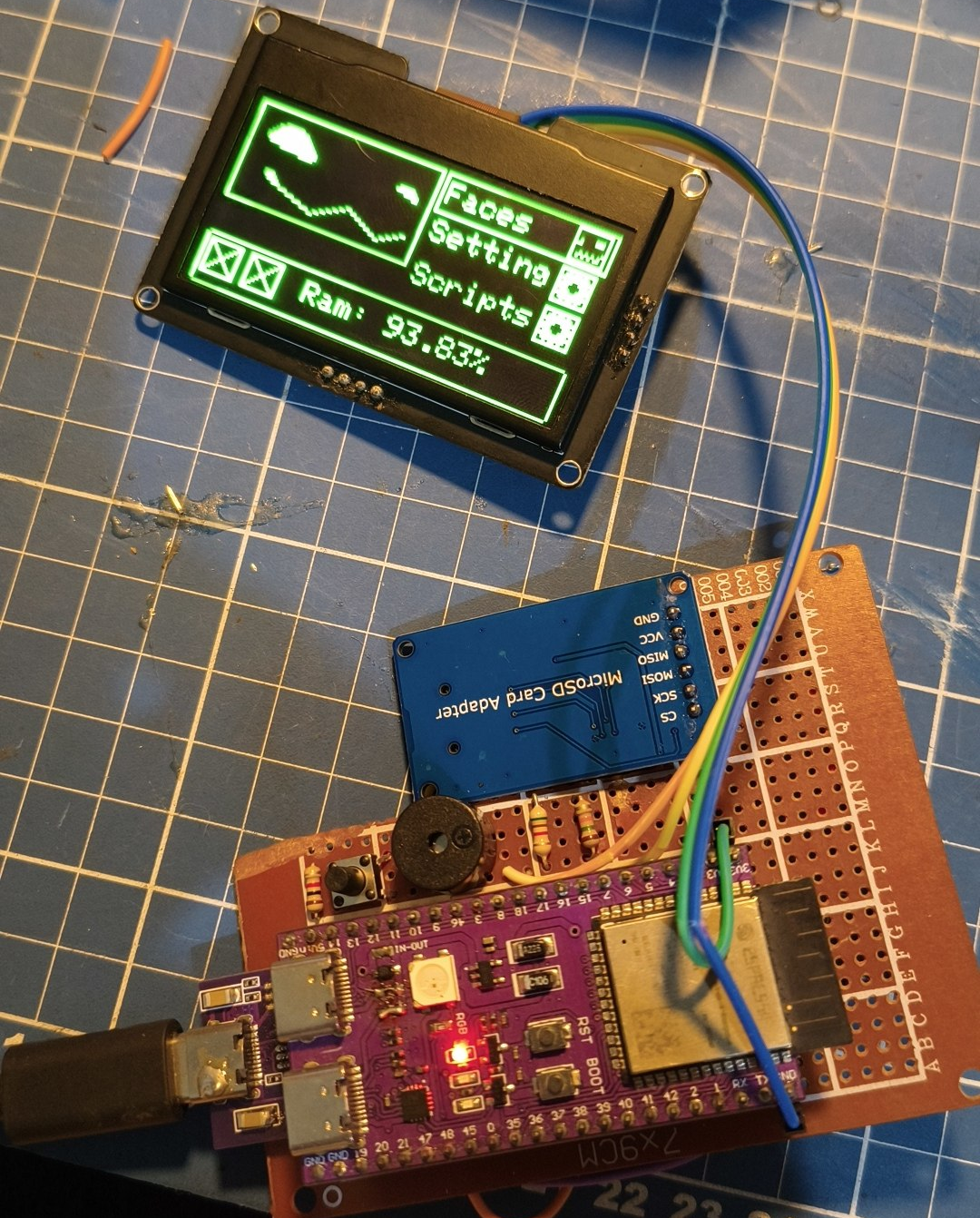
At this point you can connect the remote controller and play as you want with it!
If you’re using the same module I’m using in the photos, connect the VCC to 5V instead of 3.3v. This module has a regulator and requires 5v to operate.
HUB75 screen
This is the most complex part, because you have to solder like 13 wires to GPIOs. There is so much room for error, so do it SLOWLY and triple check if you’re connecting it correctly.
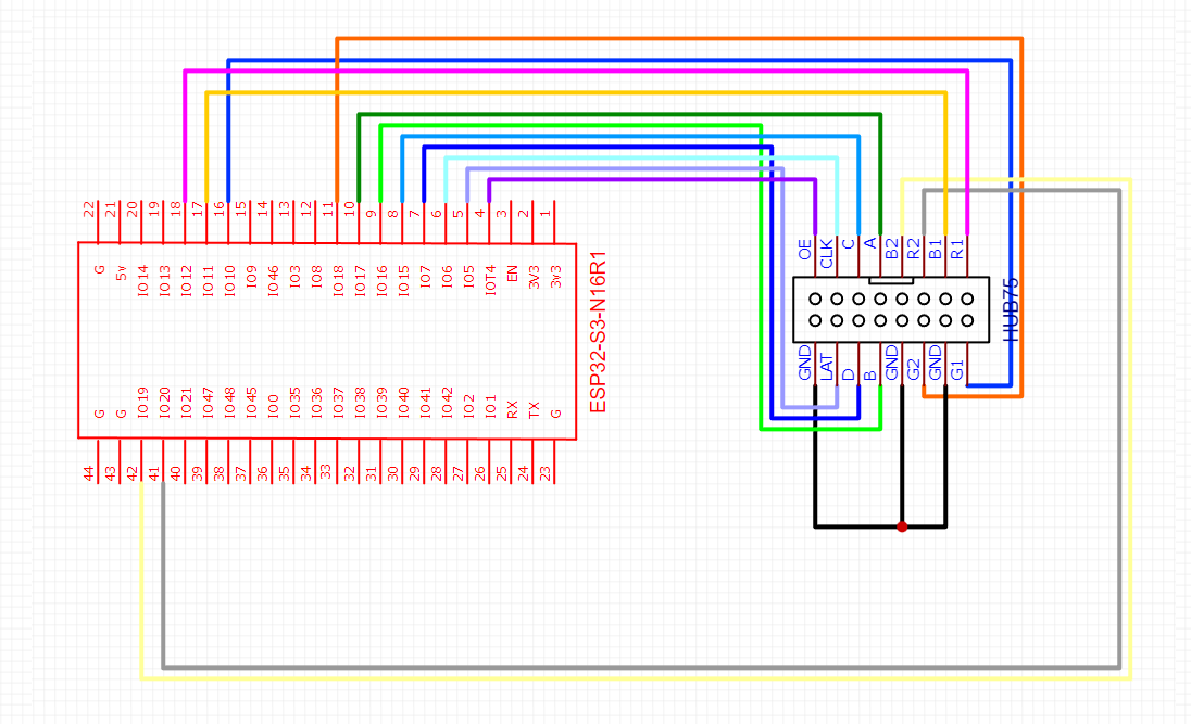
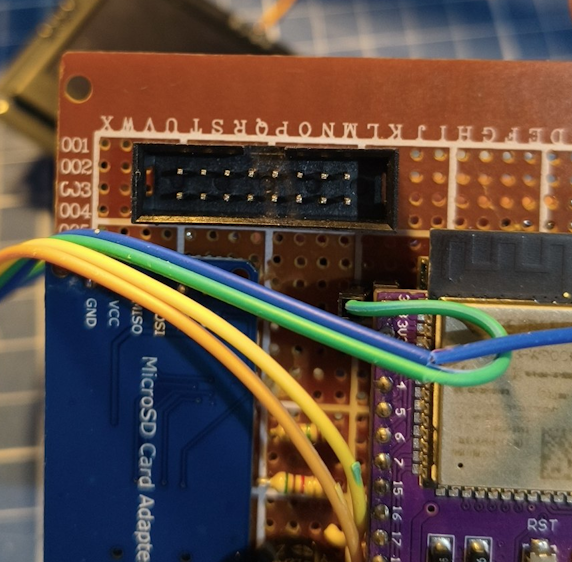
A good idea is to start with the black wires (GND) so you have a visual reference.
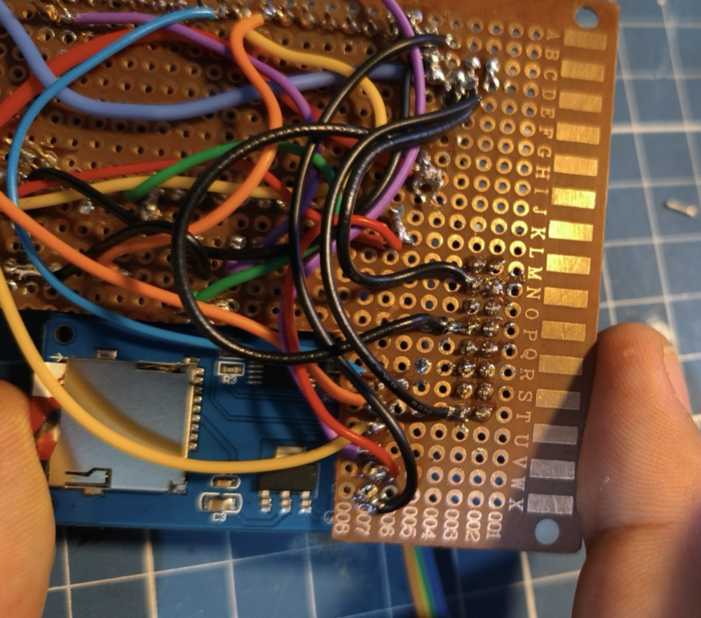
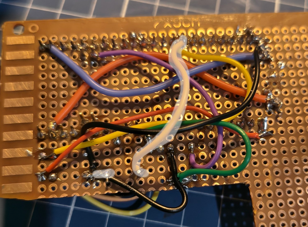
Then after you painfully solder all wires, it should look busy like this.
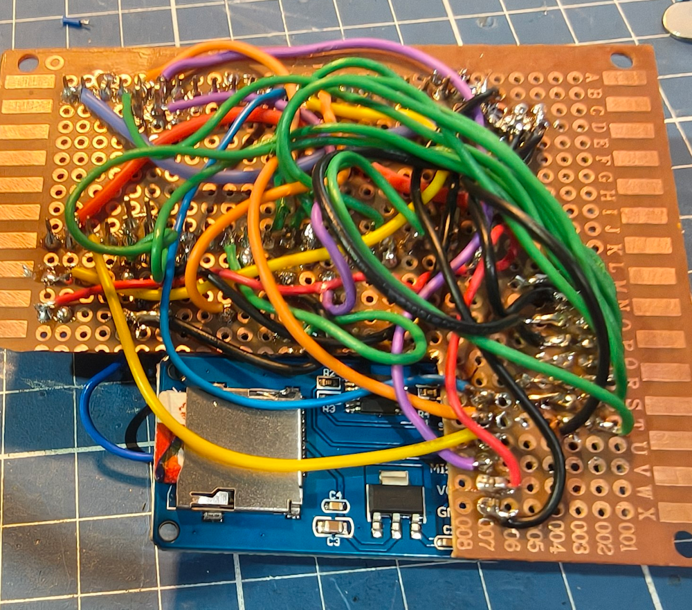
Remember you can still put some wires on the other side of the board.
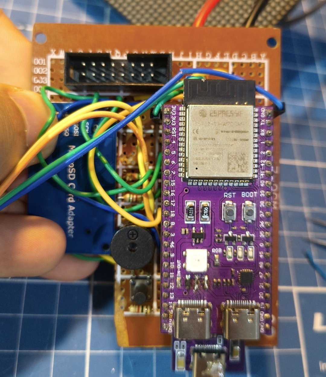
Before testing, let’s make sure all wires are connected! Put your multimeter in continuity mode and test EACH PIN.
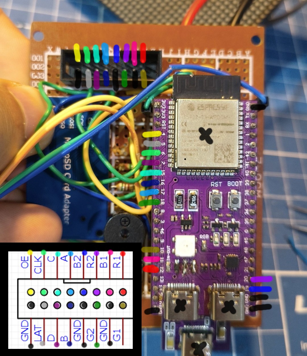
Important: The wiring above is looking from up to down. If you plug jumper cables directly in to the HUB75 cable and make it facing you, thata will make the left and right sides to be flipped!
Now that you’ve made sure every pin is correctly connected, let’s wire the power for the panels. Get the power cable that came with the panels and cut their tips.
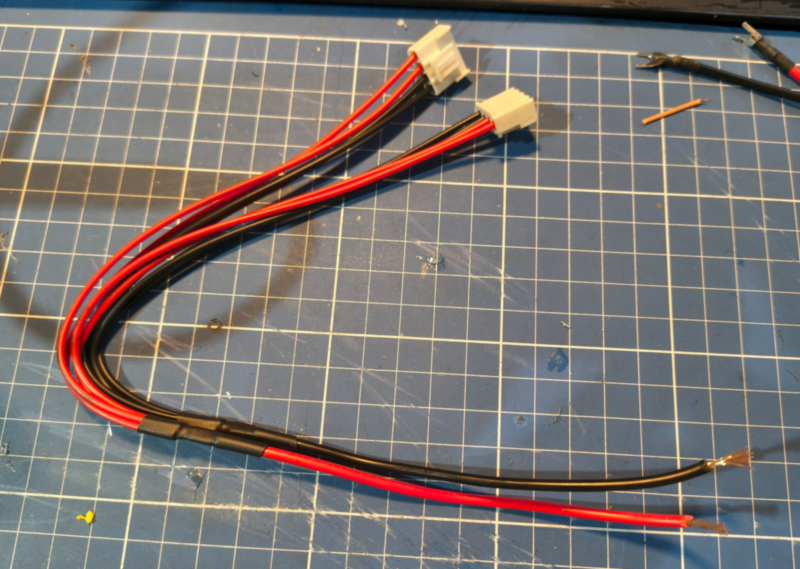
Now they should go in the 5V and GND.
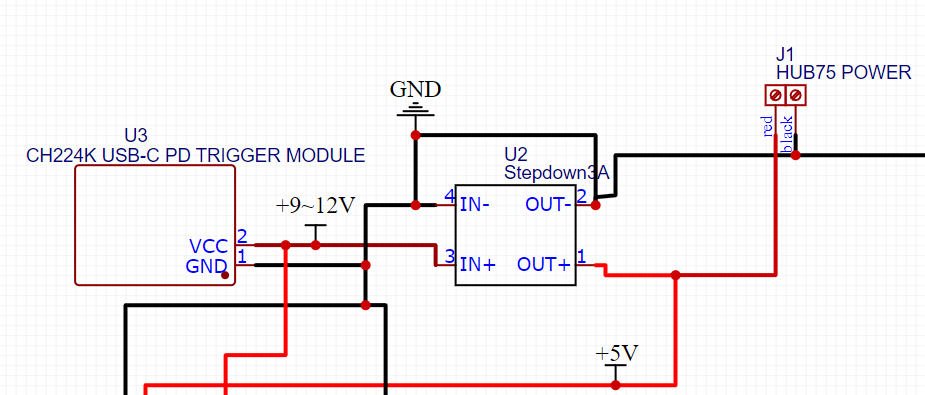
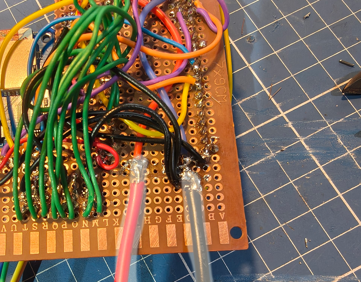
Now, make sure it’s connected to 5V, measure the output and it should be 5v. If this is correct, then plug off everything and connect the panel cable and power.
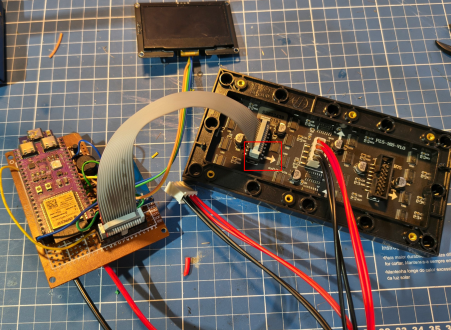
Power it on and you should see it working!!