Front frame
Here you will learn how to assemble the front frame. Note that some parts can be a little different if you are doing a DIY protopanda instead of an assembled one with the PCB.
- Tools
- Panels
- HUB75 Cables
- Power cable
- Other cables
- Internal screen
- Boop sensor
- Cooler
- Second panel
- Fur support
- Connector cover
- Fresnel lens
- USB Cable
- Materials
Materials
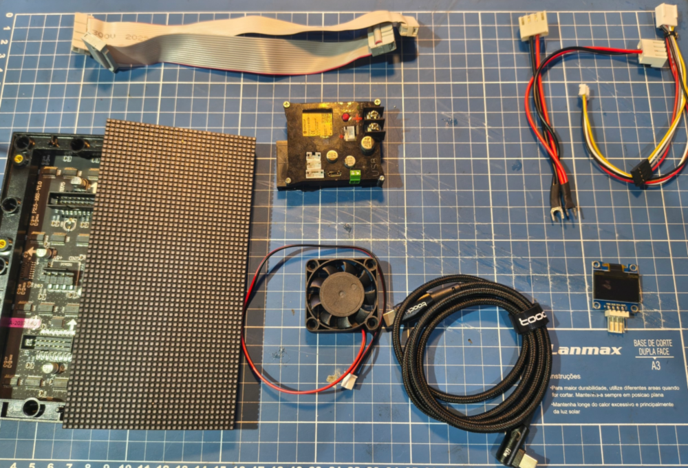
The first and most important material is the printed front frame for the P2.5 matrix.
Then you will need the electronics:
- 2x P2.5 HUB75 led panels
- 2x HUB75 cables (usually come with the panel)
- 1x double cable for the HUB75 matrixes (usually come with the panel)
- 1x 4010 5v 40mmx10cm fan
- 1x USB cable
- 1x 0.96 inch oled screen
- Some cables
- 4x M2 6mm screws
- 4x M2 nut
- 2x M3 16mm~18mm
- 4~6x M3 8mm screws
- 2x M3 nut self tapping
Optionals
- 2x IDC 8x2 terminal
- 2x M3 nuts
- 2x M3 8MM screws
- 2x M3 4MM screws
- Fresnel lens
- KF2510 Get the 4 pin one.
Tools
- Screwdriver
- Tools for crimping and crimping terminals (depends on how you gonna do it)
Asembly guide
Panels
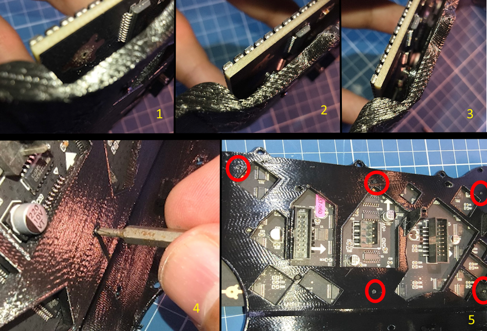
First we need to disassemble the panels to remove the original support. Use a thin screwdriver There are a total of 6 screws, they’re really tiny, so be careful and save them.
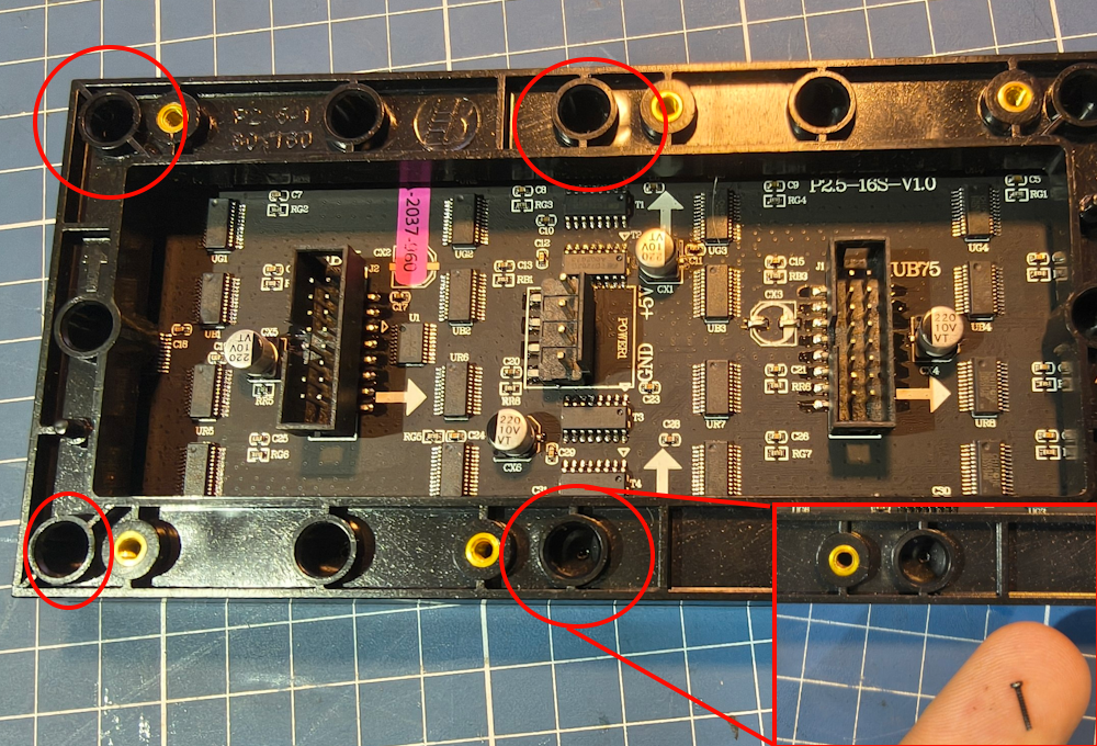
Once removed take off the support.
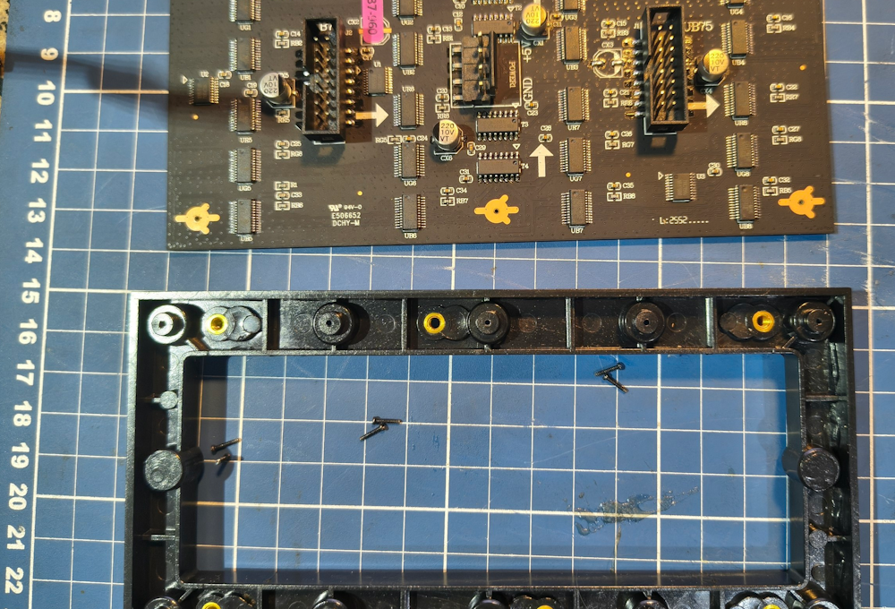
Now its time to put one of the panels in the LEFT side of the frame.
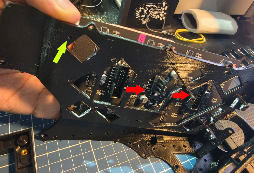
There is a correct orientation of the panel. Note on the panel there are white arrows. Align them facing forward like the red arrows. Also align the panel uusing that hole pointed by the yellow arrow.
Then follow those steps: 1) Align the panel 2) Place the screw in the hole 3) Push the screw and align the panel 4) With a small screwdriver or a screwdriver bit, tighten the screw. DONT TIGHTEN THEM TOO MUCH, just enough for them to stay in place 5) Do it for those 5 points highlighted in red.
HUB75 Cables
Now its time to install the first cable. This cable will transfer the signal from the first panel to the second one.
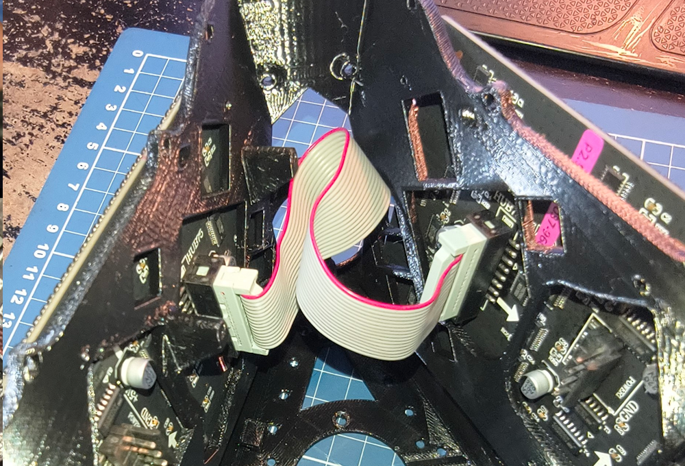
But as you can see, theres a bit too much cable in there. You can leave it as is, or you can trim the cable down. Thats whats I’ll teach you right now. But please pay attention on what you doing, if you wire them backwards you will certainly destroy one or both panels.
If you want to leave it as is, skip to Power cable
As you can see, the cable has about 19~20cm. But we only need at least 11CM.
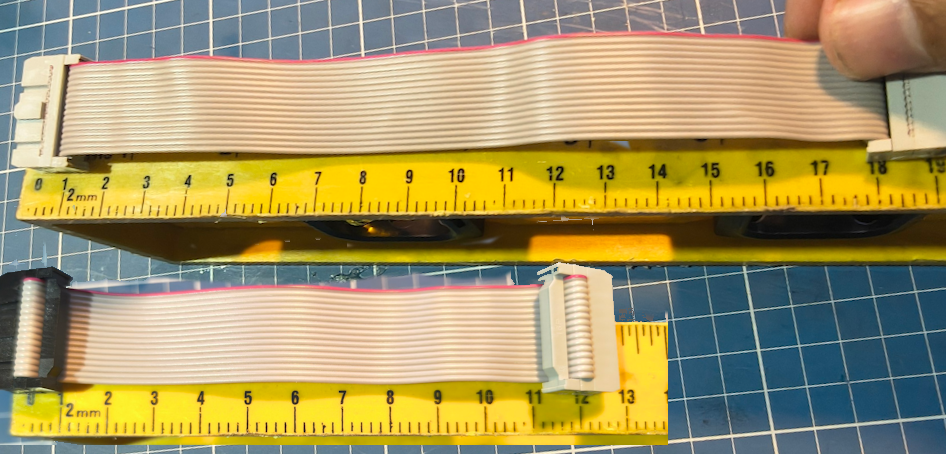
Then for that, you will need to cut the cable at about 13.5cm~14.5cm
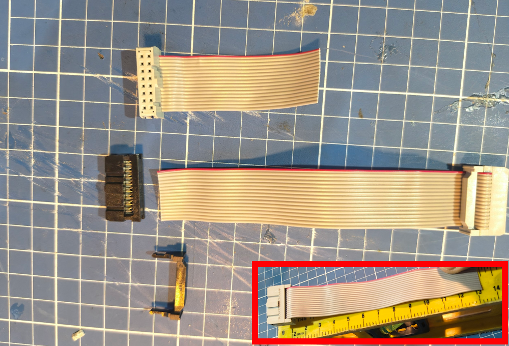
Then grab the IDC terminal and put it in the correct orientation. DOUBLE OR TRIPLE CHECK THE ORIENTATION BASED IN THE ORIGINAL CABLE
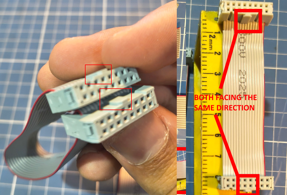
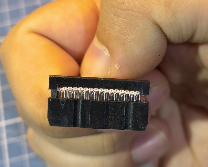
If you need extra help, try googling on how to crimp idc connectors.
Power cable
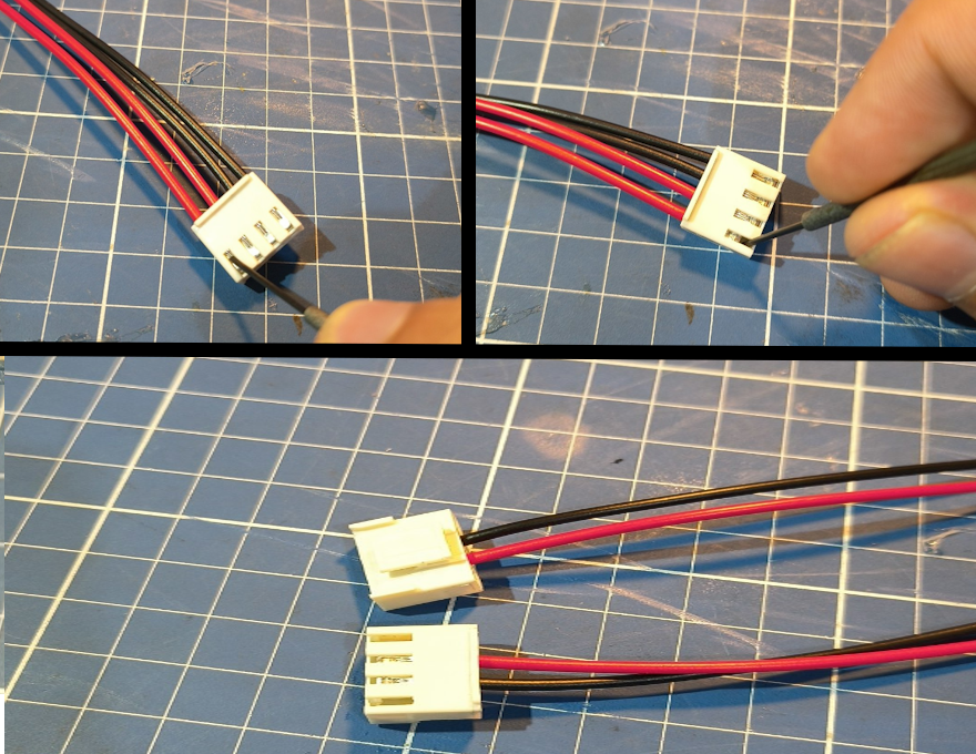
For powering the HUB75, you can use the original cable. But its bulky and too long. So you can trim it down.
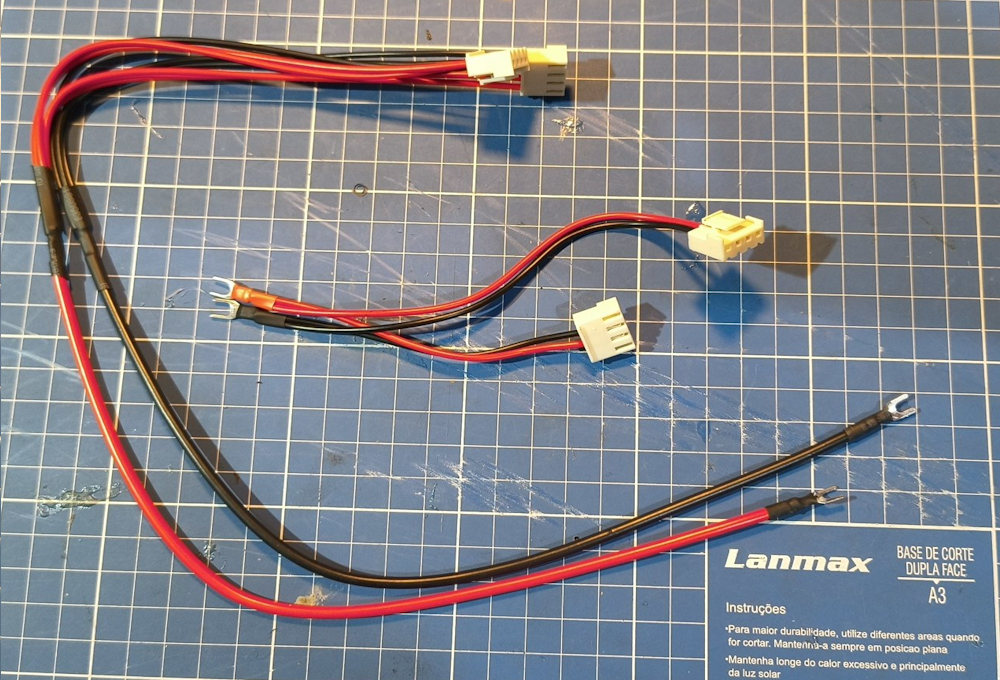
Then cut right when it joins with the other cable
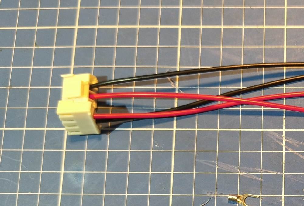
After that remove the extra terminals, we only need one black and one red on each of those two.
Then strip about 1cm of each wire, twist them together, put a shrink
wrap on each of them and crimp a fork terminal like this: 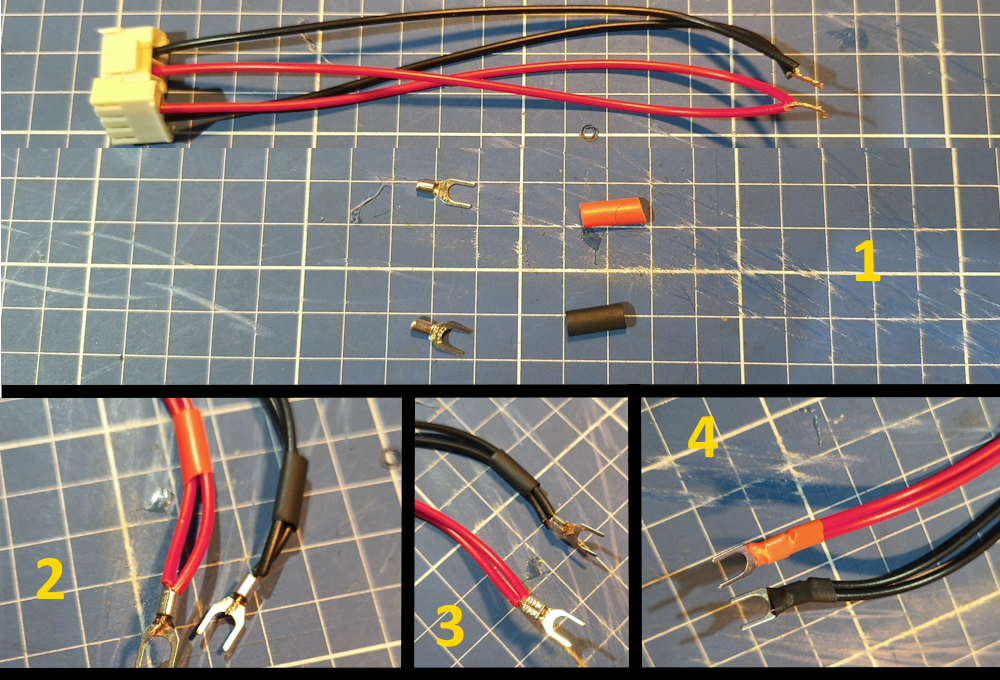
Thats how they should look like:
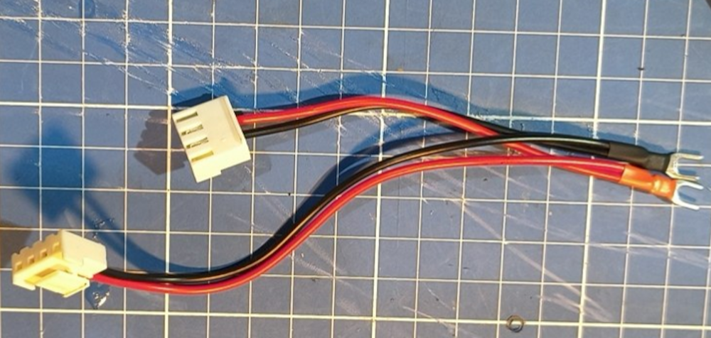
They go in the protopanda at the screw terminal.
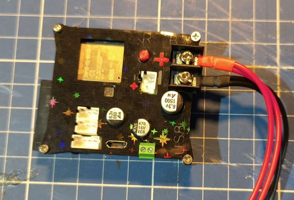
If you’re doing DIY route, then go at the schematic where is written HUB75 POWER In case it isnt clear, red means positive and black negative.

Other cables
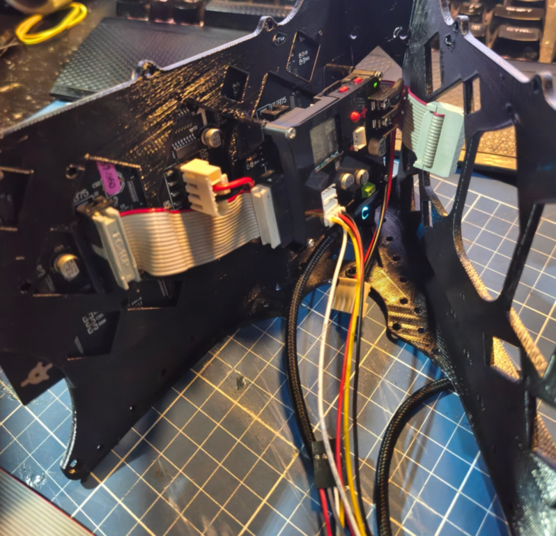
Now its a good idea do plug in the other cables.
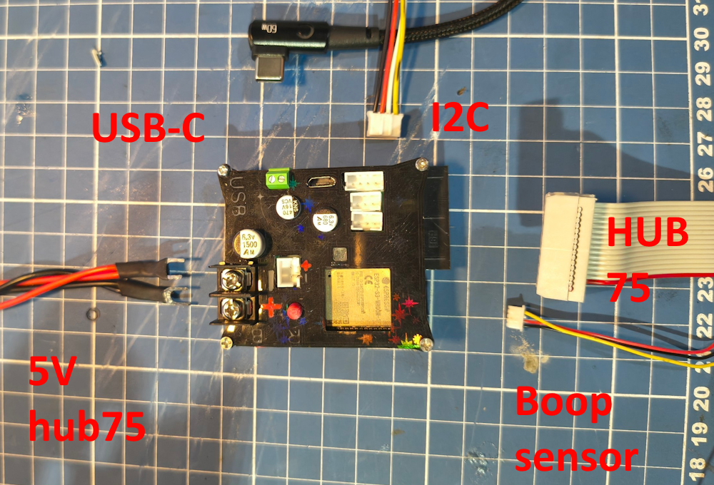
If you doing the DIY route, you can choose any kind of connector you want, or just wire directly to the display and boop sensor. I used PHT connector but that was my prefference for the way I did. Do it your way!
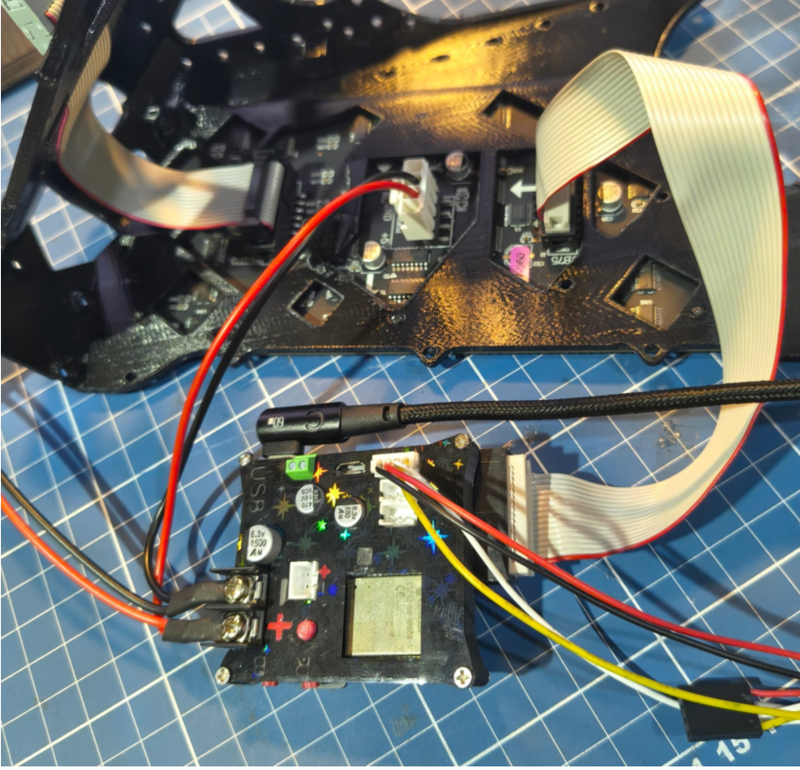
Specifically for proto panda controller, there is a spot dedicated to it. But the DIY route might take up more space. That part will depend heavily on what and how you built it. The screw holes are M2.
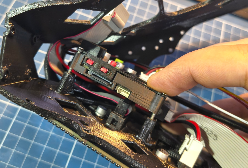
With a long screwdriver you can each all 3 screws.
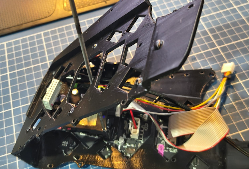
Then it should look like this.
Internal screen
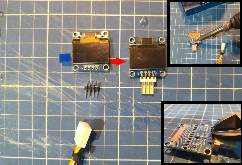
You can totally use the screen with the pin header. But personally, i like to use those KF2510 connectors.
I soldered the 90 degree connector and cut off the pins that came out the other side.
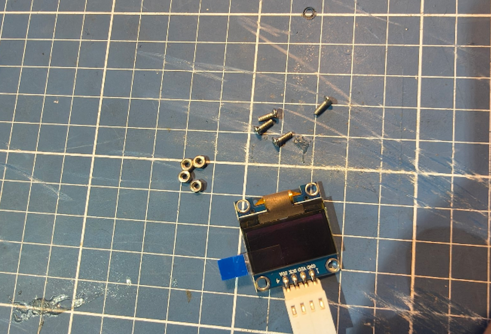
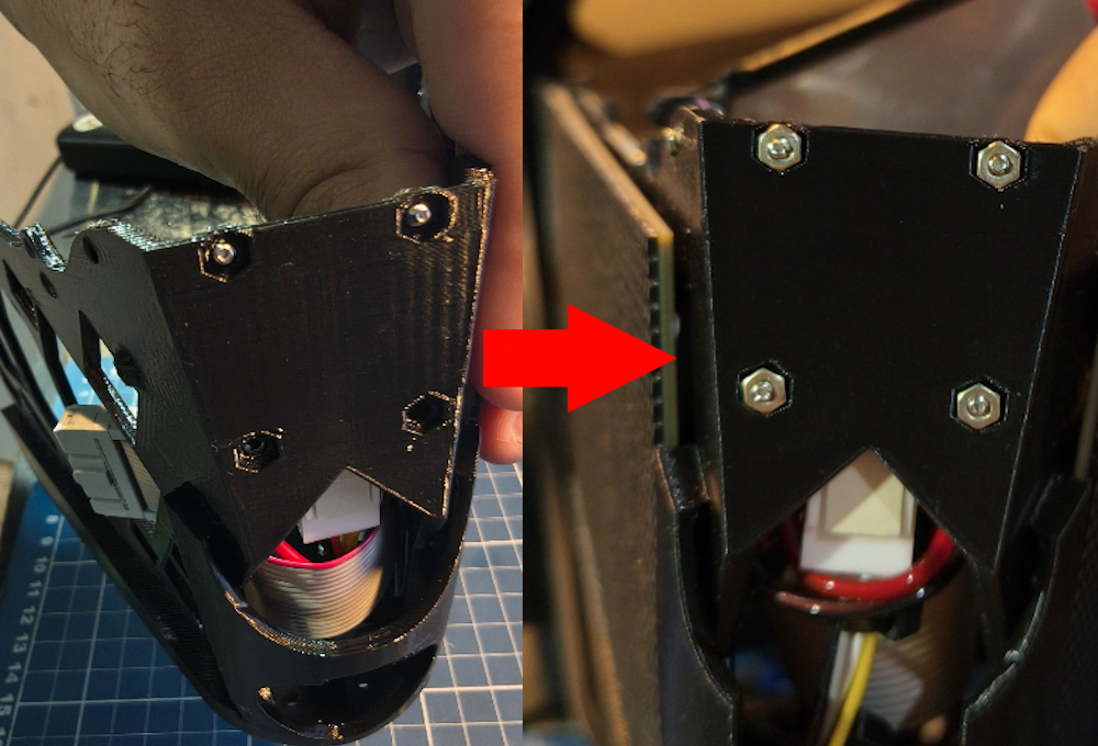
Then grab the screws and the nuts to attach it to the frame:
Put the screws trough the holes
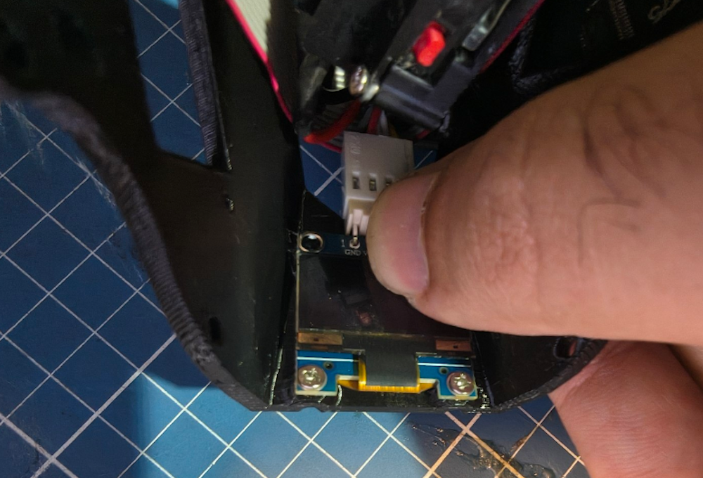
And screw them tto the nuts at the other side
Boop sensor
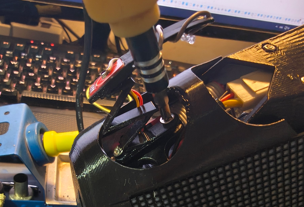
There will be a guide to make the boop sensor in the future. I’ll do it I swear! For now it’s just the capacitive sensor with some wire wrapped around it.
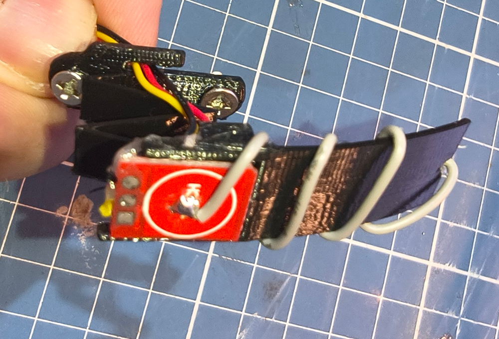
Attach the boop sensor to the front of the panel
Cooler
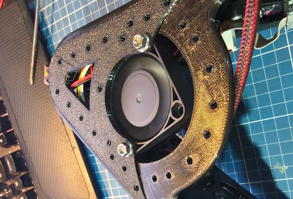
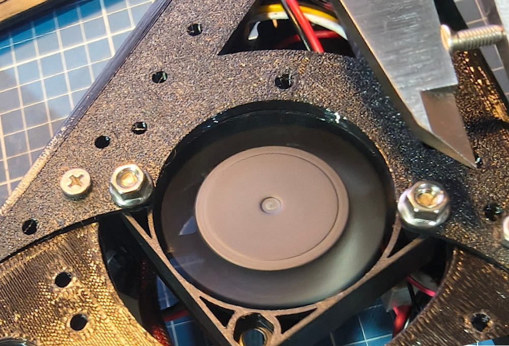
For the cooler, we’re using 2x M3 16mm and the nuts. First connect the fan to the socket. If doing the DIY route, use the same pins as the HUB75 power.
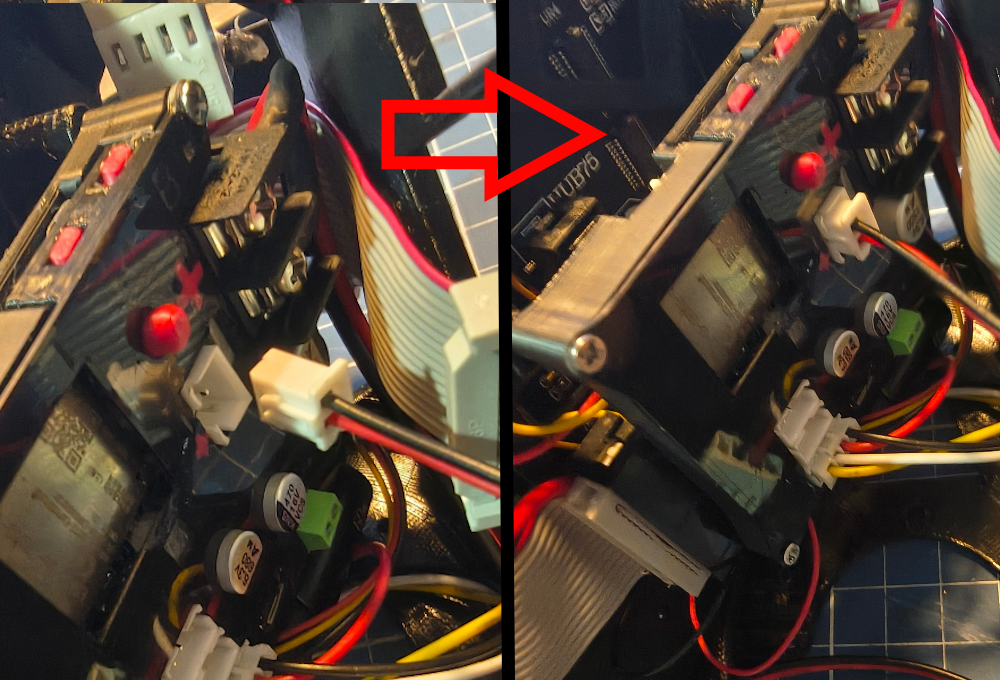
Then place the fan on the bottom of the front frame, with the wires facing forward.
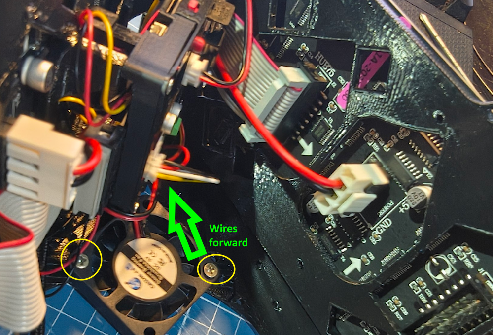
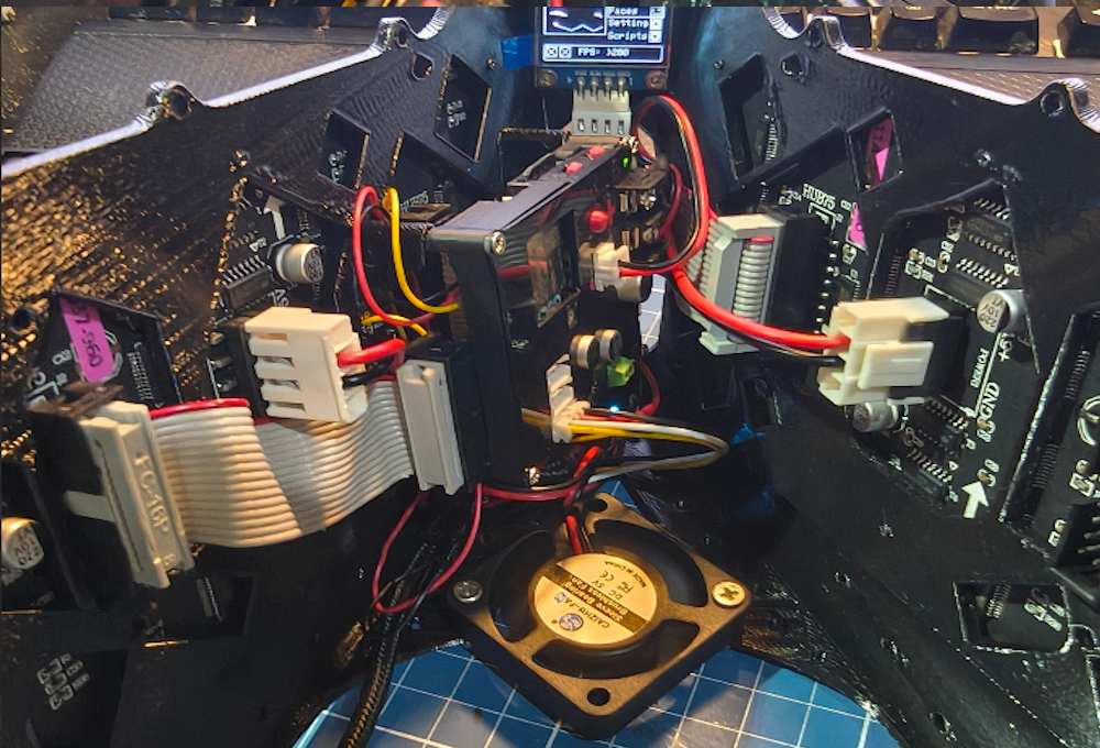
Use the nuts at the bottom part and tight the screws.
Second panel
Now we’re not fiddling with any more wiring, let’s connect the last cables on the second panel. PAY ATTENTION TO THE DIRECTION OF THE ARROWS IN THE PANEL.
There shold be 4 screws to fix it in place. They are circled in yellow.
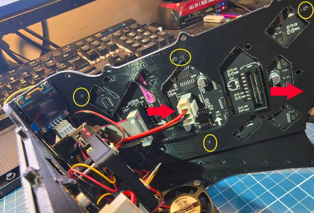
No need the 5th one. The process to align the panel is the same as the previous one.
Fur support
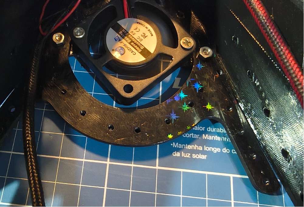
In case you need a place to sew or attach the fur, there is a support.
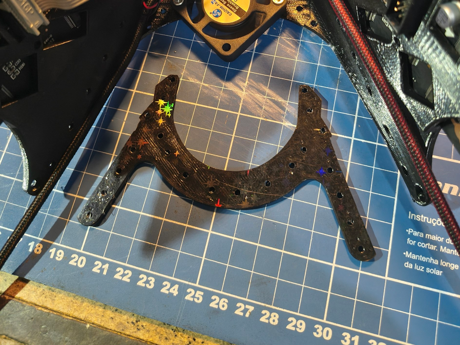
Use the M3 8mm screws and the nuts to fix it in place. It should snap in place but needs the screw to stay there.
Connector cover
Since we dont wanna damage the HUB75 connectors with our cheeks, lets add a cover for them. Use 2x M3 8MM screws to fix it on the front frame
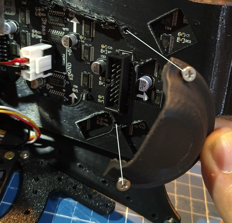
It should look like this:
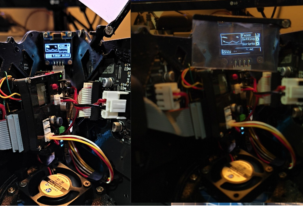
Fresnel lens
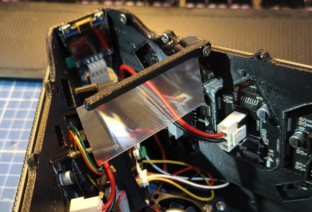
The fresnel lens is completely opitional but a nice to have. Without it might be hard to focus your vision at the internal screen. With it is way way easier. The effects are mostly in person.
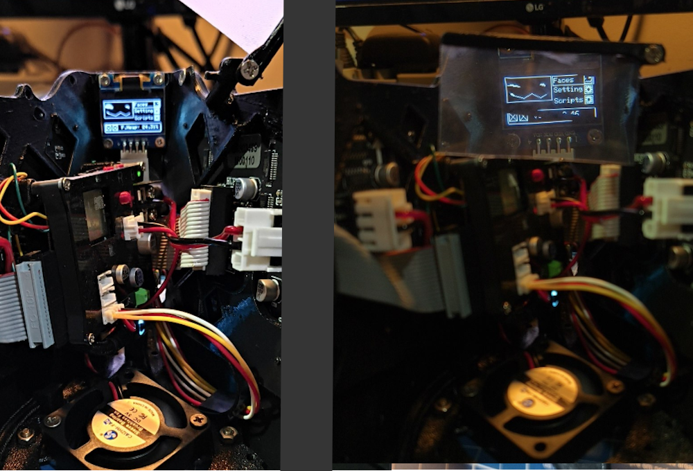
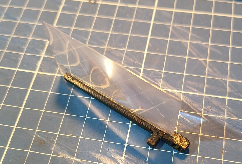
For assembling it, you will need to cut the fresnel in a 64x34cm rectangle. Glue it in the 3d printed slot using super glue (JUST A TINY DROP)
Screw a 8MM M3 screw to attach both parts together
,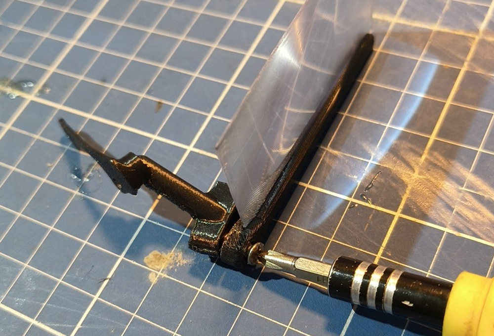
Then use the two M3 5MM screws and put them in the hole of the other part
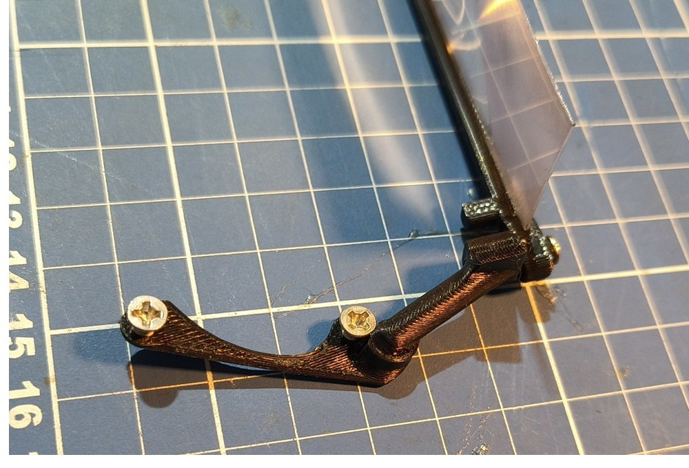
Now align it in the front frame. It goes at the internal right top part of it.
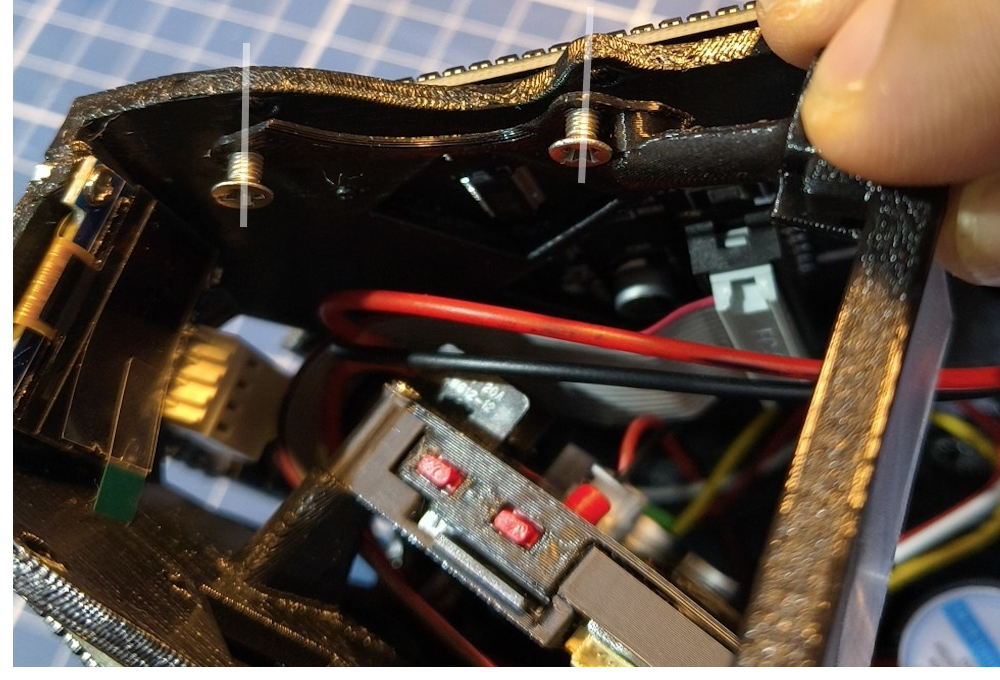
Then screw it in place and you will have a fresnel lens that can be moved up out of the way when the visor is not there, or simply unscrewed in case you don’t like it!
USB Cable
Now for the USB cable. In the material list I asked for a 90 degree USB-C. There is not much space for a straight USB cable there, and that might force the cable or the connector. Even the side facing cable can have a lot of strain on it.
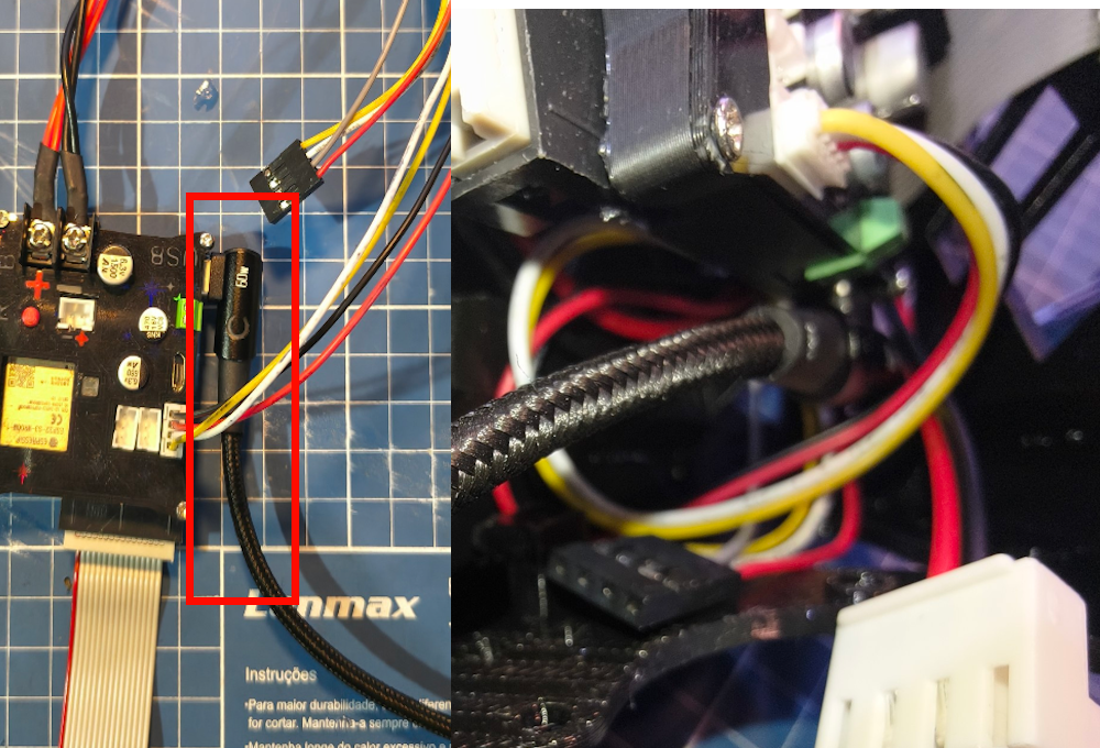
That’s why we will place it in a slot.
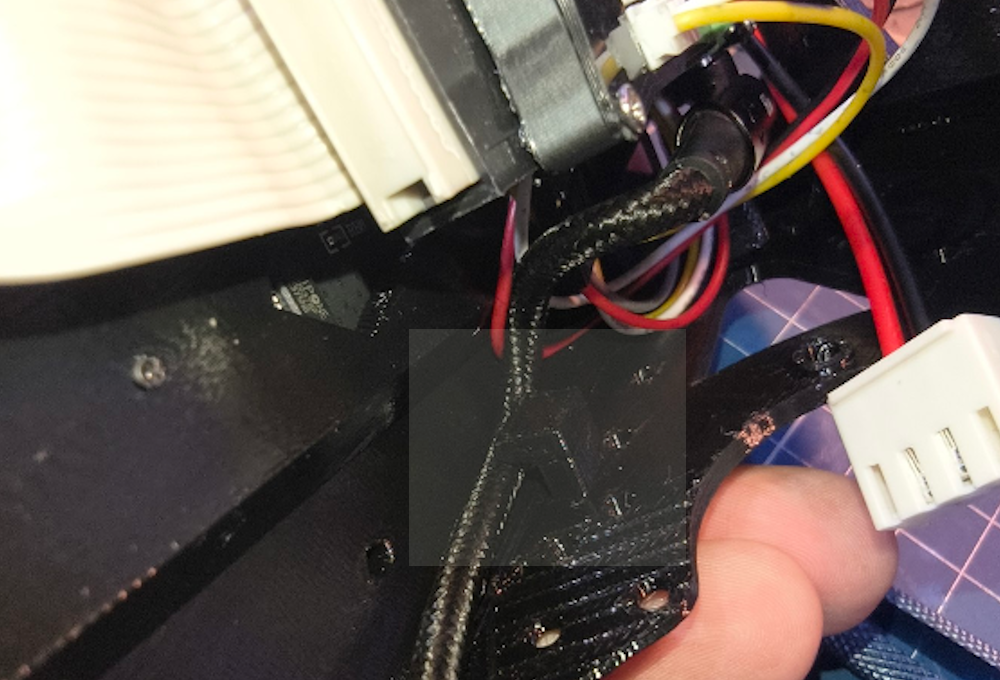
Make sure the cable is going inside that slot and doing a little curve inside. If needed push it a bit inside,
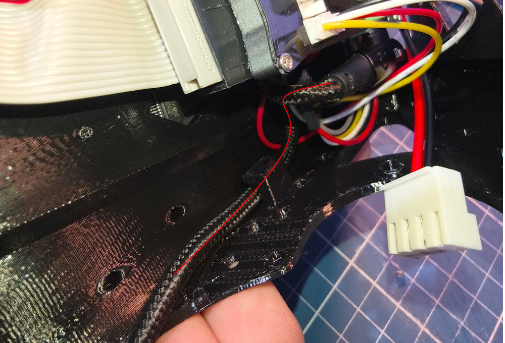
IT IS COMPLETE!
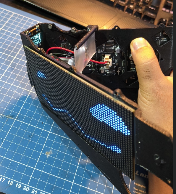
There you go! You completed it!!