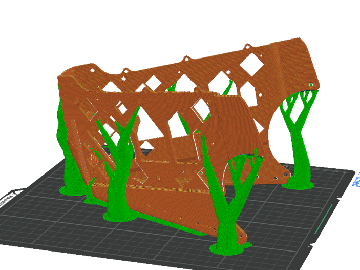
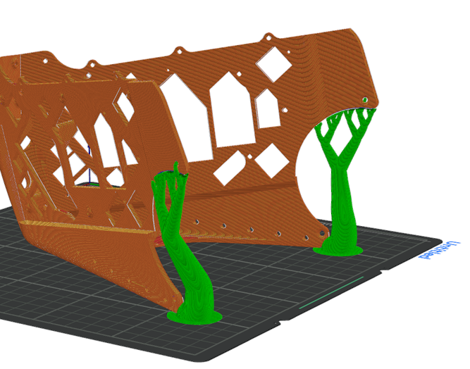
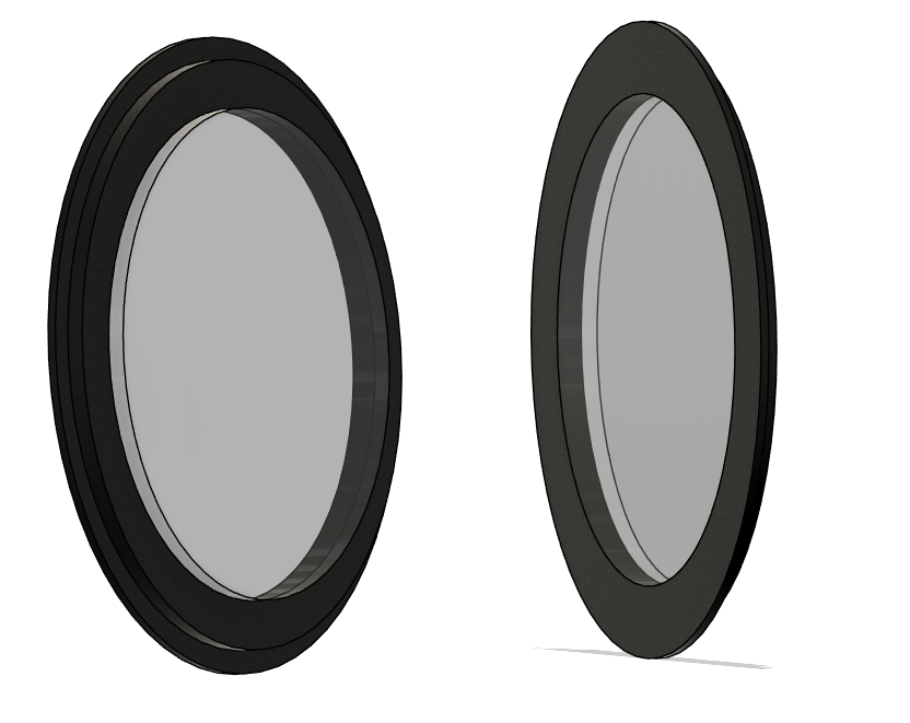
Printing protopanda is easier than the original MK16 model. It requires less support and has some features like to reduce the amount of material used.
It also adds a bit of complexity in other parts, so it may look nicer, or have more features. Any of those parts are interchangeable with the original MK16 model.
You can download the models here
The basic requirement is a 3d printer with 25x25cm bed. Generally speaking, the whole set can be printed entirely in PLA. But that is not reccomended for some parts due strenght issues. Be aware that PLA under directly sunlight can bend and warp, also it can easily become maleable on temperatures over 50ºC.
Some parts of the guide will reccomend using ASA or ABS, but they're toxic while printing. Weight your decisions and needs.
Bellow you can click on each of those images. Each session has a printing guide, reccomended settings for each part, tools and accessories necessary and assembly guide.
| Front frame | Headphones | Back head |
|---|---|---|
|
|
|
| Materials | Materials | Materials |
| Printing | Printing | Printing |
| Assembly | Assembly | Assembly |
| Led holder | Clips | Ears |
|---|---|---|
 |
 |
 |
| Materials | Materials | Materials |
| Printing | Printing | Materials |
| Assembly | Assembly | Assembly |
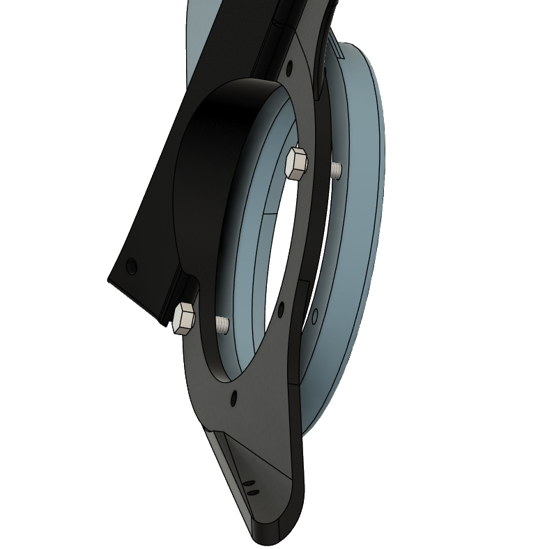
| Joining all parts together |
|---|
 |
| Materials |
| Assembly |
Almost all parts that require screws can be glued instead. The original MK16 does that. With exception of the front frame. * Two component glue * 10x M3 heat insert (5~7mm in height) * 18x M3 heat insert 3mm height * 8x to 16x M4 heat insert (5~7mm in height) * 8x to 16x 10~15mm M4 flat head screws * 4x M3 flat head 10mm screws * 12x to 18x M3 6mm screws * 2x 10mmX2mm neodimium magnet * PETG, ASA and TPU * Transparent PLA * Black PLA * 2.7mm~5mm ws2812b led strip (or a 5x5 led matrix) * Super glue * 3 pin PH 2.0MM connector with wires (or some other 3 pin connector)
Back to top ## Headphones Materials
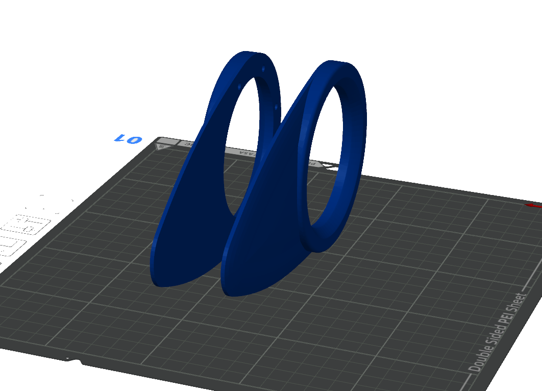
The headphones can totally be printed in PLA. It will come out nice and it don't have thin parts that can easily break or crack. Ideally use ASA. You can use PETG, but petg is notoriously hard to sand and just a little moisture can make your primes come out like garbage. Prefer something easier to print here
Place the part with the back facing the plate like this 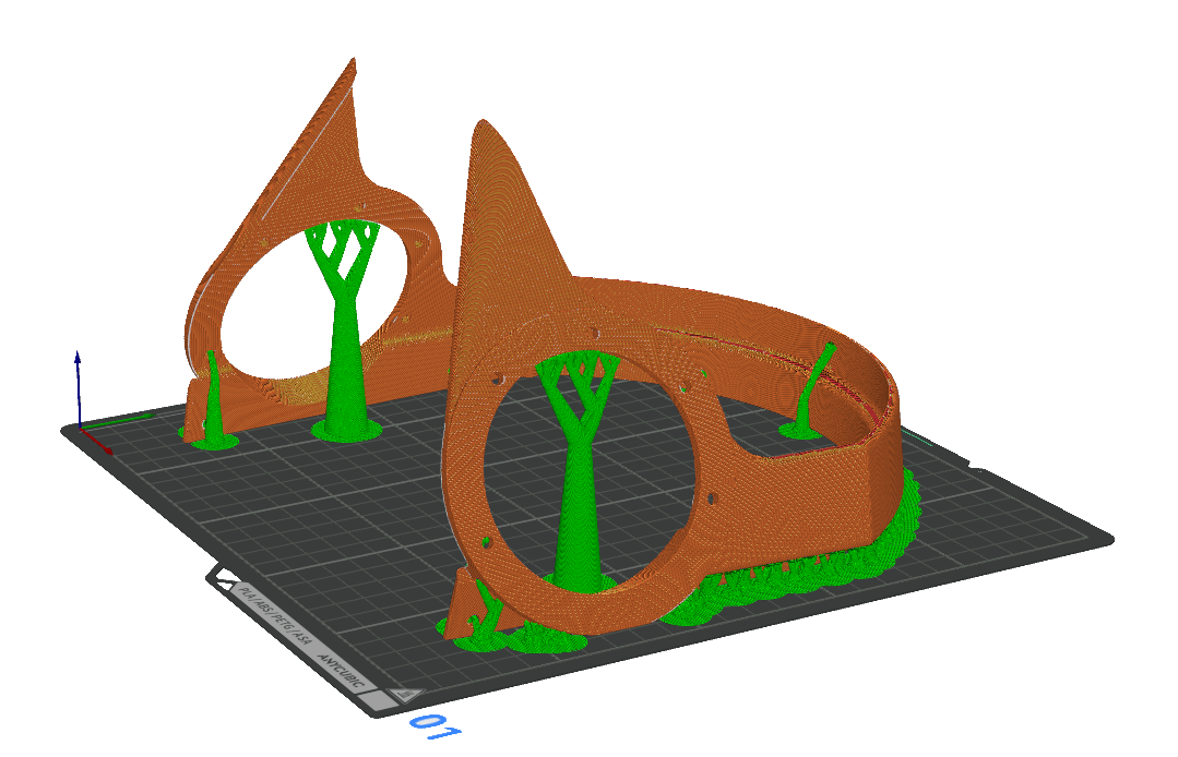
The fins can totally be printed in PLA. It will come out nice and it don't have thin parts that can easily break or crack. Ideally use ASA. You can use PETG, but petg is notoriously hard to sand and just a little moisture can make your primes come out like garbage. Prefer something easier to print here
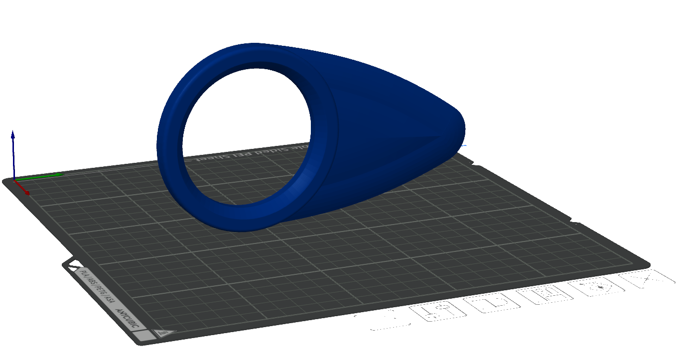
Once you load the STL file it will probally show in a wierd angle. 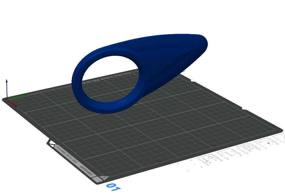
Then will be needed to place it flat. Select in orca the tool to place it flat and choose one of the regions
Fins
Select some area on this region: 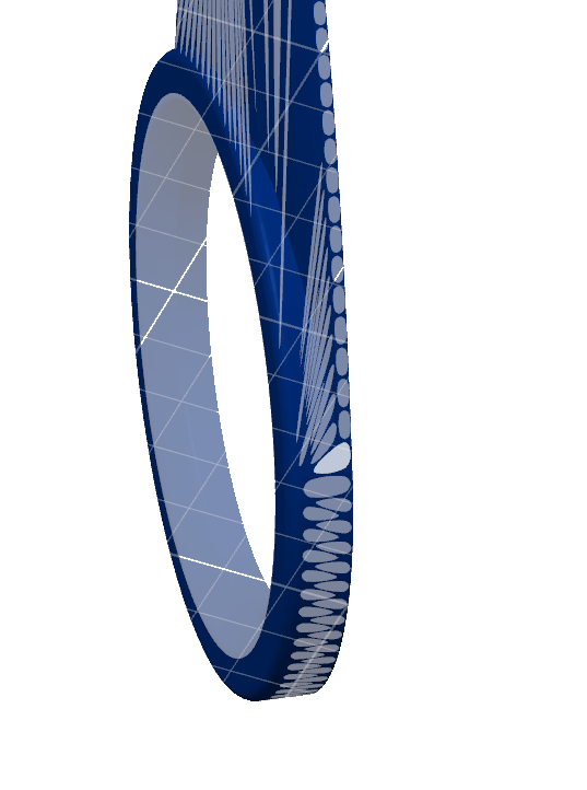
It should look something like this when placed
Fins
You can order to print like this, but lets be efficient. Create a copy of the model by selecting it and pressil ctrl-c and then ctrl-v. Then right click on the new body and select mirror then mirror on the Y axis. If they are too close, move them apart. Should look like this:
Fins
When printing it should look like this:
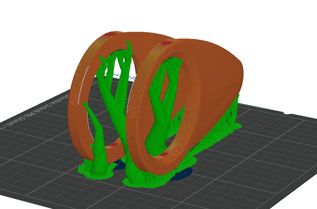
Fins
If you see the plastic sagging at the tip of the fin, increase the support treshold angle or add a "support enforcer on the tip"
BUT MOCK, CANT YOU PRINT IT WITH THE BACK ON THE PRINT BED INSTEAD???? Yeah. You can! But the original mk16 fin has some soft curves that most printers will striggle to replicate with that orientation. Thats a great idea if you have a custom fin with a flat surface. 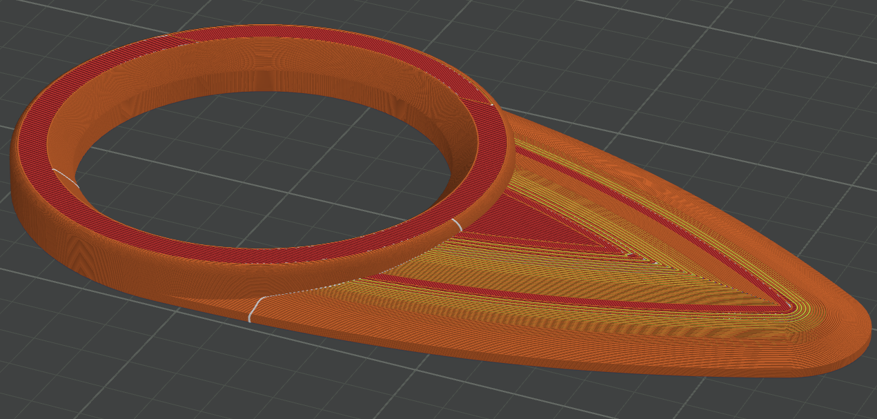
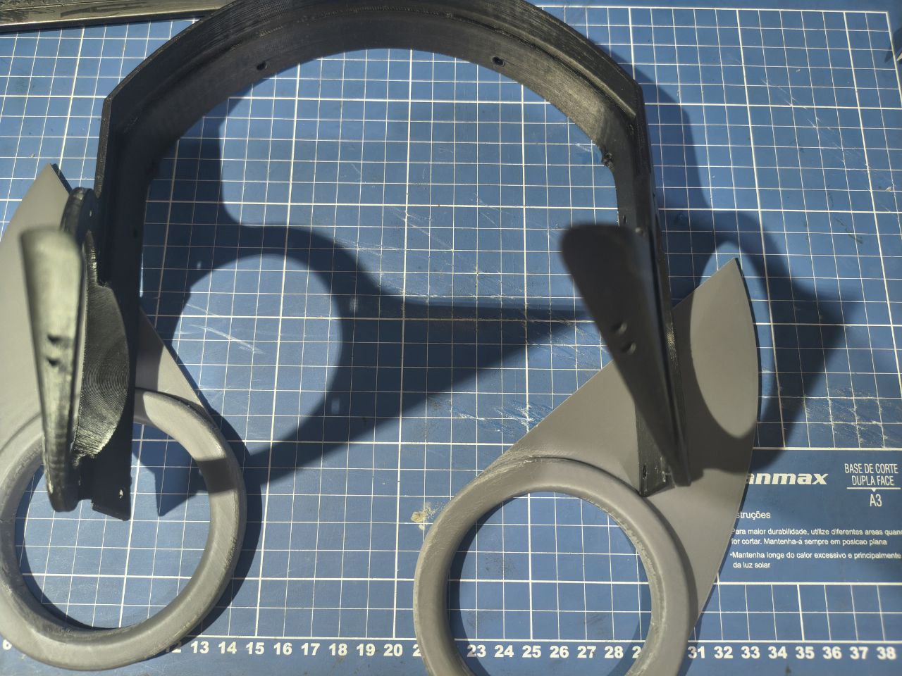
Now that you have all parts, now its a good time to sand it and trim all the support parts that got stuck. Doing it later will be harder.
Headphones
Now grab two of the M4 screws, put them in two of the holes of one side until they come out on the other side. Use them to align the fins like this:
Headphones
Retract the screws until the fin touches the headset. Screw the scres in to make sure they enter the fins holes. This is only to get them aligned. Do this for both sides.
Once you get it right, its time to mix the two compound glue and make sure its well mixed.
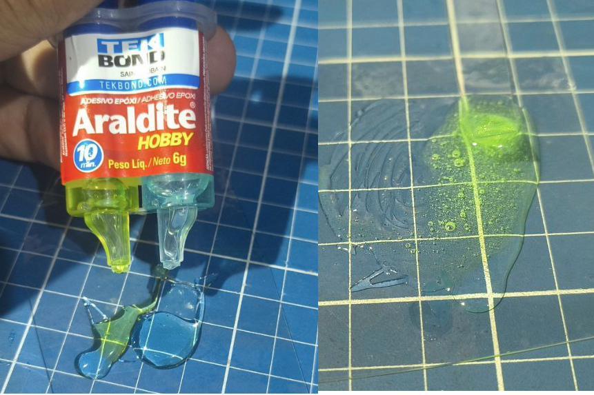
Headphones
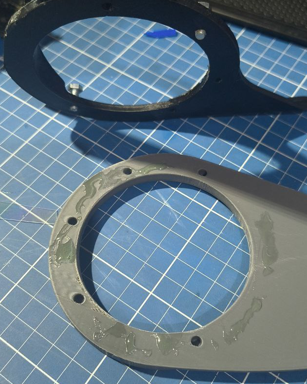
Now spread between the screw holes on each of the fins. Avoid putting too much and avoid putting too close of the outer edge or the screw holes. Putting too much or too close will cause the glue to get smushed and leak trough the outer side... Which you will have to clean it up. Glue on the screw hole will make you have a hard time taking the screws off and putting the heatset.
Save some glue for the magned in the top of the head.
Headphones
Now put both of the fins in place and use the screws to keep them aligned. Dont screw it all the way in
Headphones
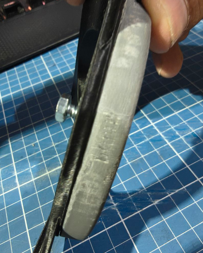
If you notice the screws not beeing enough to get the fins completely straight and touching the whole sides, use the c-clamps to keep them close
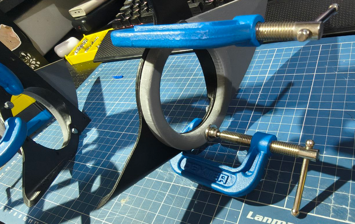
Headphones
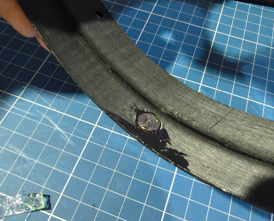
Now use the leftover of the glue to fill a bit on the hole at the top of the head, and then place the magnet there.
Headphones
Headphones
Spread some glue on top of the magnet and if you have a few leftover magnets, put them on the other side to hold it in place
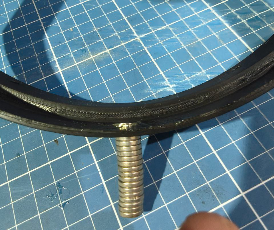
Headphones
Now its a good idea do clean any bits of glue that came out of the edges. Make sure you wash your hands very well too! Leave it still until the glue is completely cured.
tic tac tic tac goes the clock
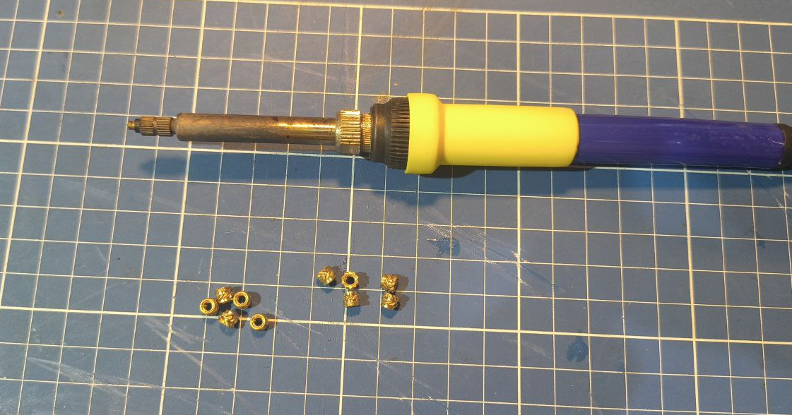
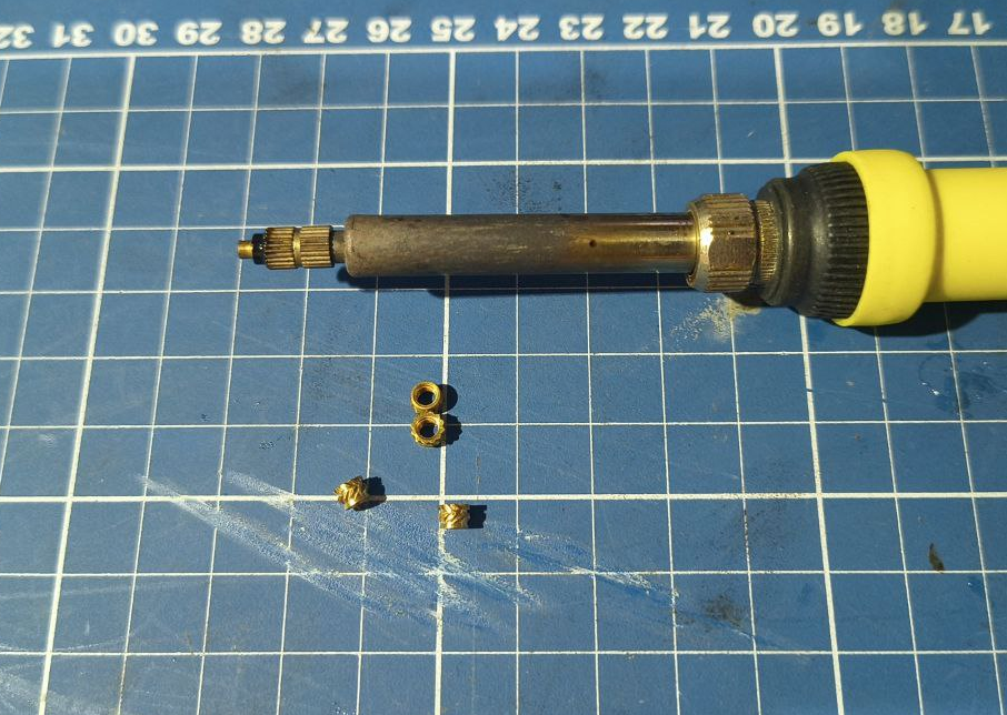
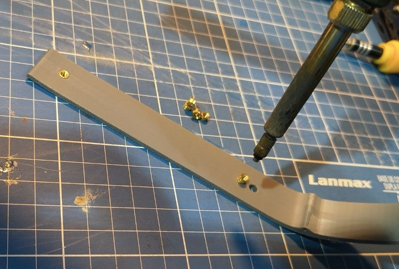
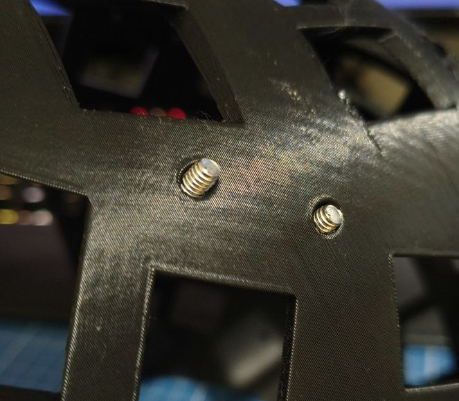
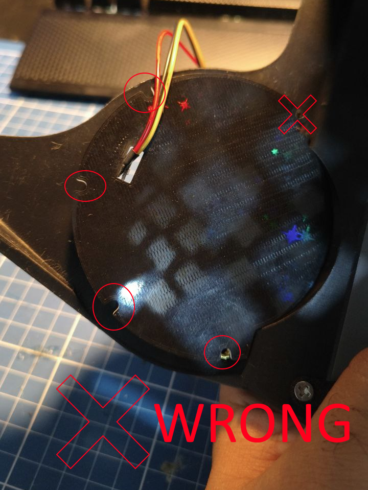
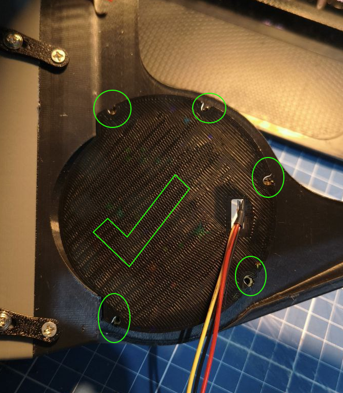
Now grab your heatsets and your soldering iron with the heatset tip and warm ir up to 300ºC (If using PLA then 250).
Headphones
Place the M3 (the long one), over the hole and put the soldering iron it, applying only a tiny amount of force. Wait a few seconds until you see the heatset going on the hole and melting the plastic around it. The apply a little more pressure, but dont go too fast. We want it to go slowly while it melts the material around it. Make it go 2 to 3 mm deep. If you got 7mm long heatset, you can go as they get to the surface. If they're 5mm, then go that deep.
Headphones
Do this for all the holes without the screws. Then remove the screws and do it for them too.
Headphones
Now to wrap it up. Get the the M3 3mm heat sets and put them on the holes in the back of the headset. Put them just enough so they align with the surface. Try to do it as straight as possible relative to the surface.
Headphones
Once you finished, this part is complete!
Headphones
Back to top ## Back head materials
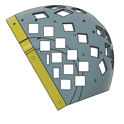
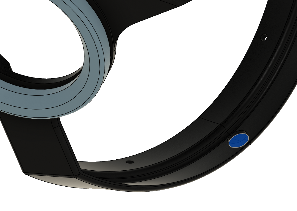
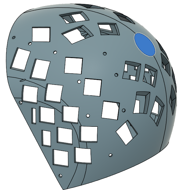
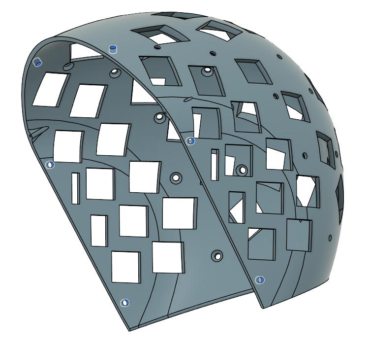
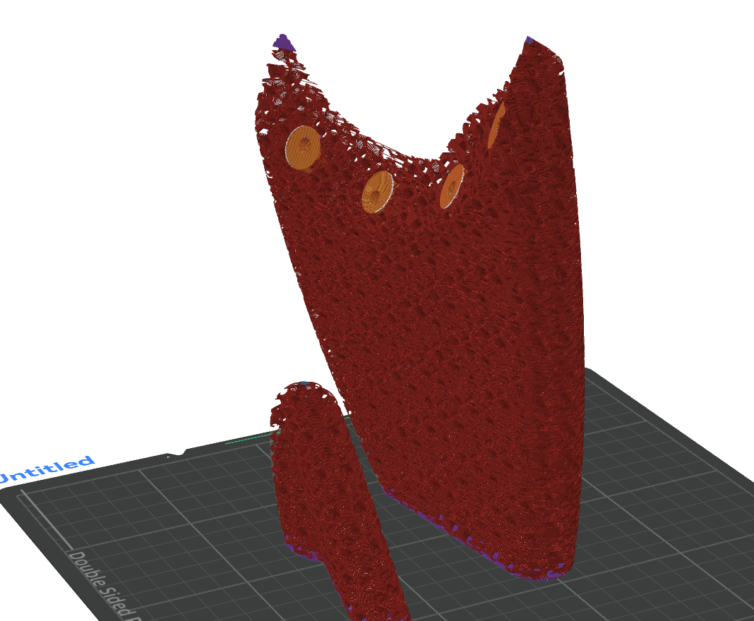
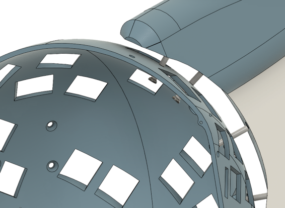
Due the way 3d printers work, we need support in certain places so the material don't just fall. Luckly you're dealing with a model that MOSTLY avoid this need! It was designed so the minimum amount of support is needed and it has holes to improve hearing, airflow and saving up on material!
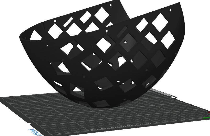
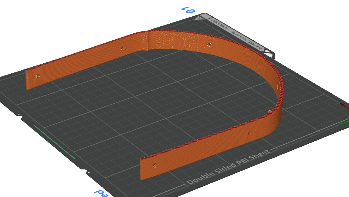
The model has a flat surface, first use the "Lay on face" to put the model facing up.
Fins
Front frame
Like this
Front frame
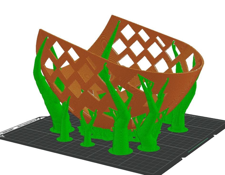
If you print like this, there is a high chance the model wobble and you get terrible results or it simply falls off from the print bed. Thats why we going to enable supports.
Front frame
MOCK. THERE IS ALOT OF SUPPORTS THERE. WHAT THE HECK?!
Yeah, those supports dont really matter honestly. They just get in the way and are a waste of material. So we need to disable MOST of them. For that, we're going to add a "support blocker".
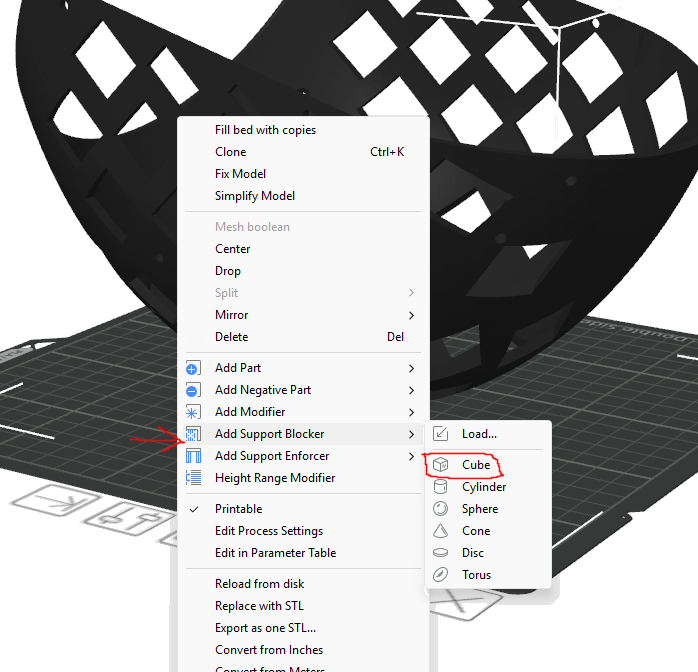
Front frame
Place it like this, leaving the bottom of the helmet like that. We do this because those supports act as stabilizers and an extra layer of adehesion for us. They should come off easily when finished.
Front frame
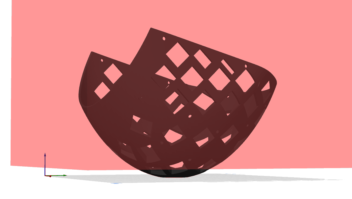
Your supports should look like this:
Front frame
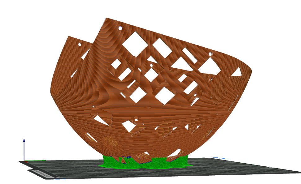
Once finished, it should be like this.
Front frame
Same process as the back head. Load the model, make it lay flat, disable all supports.
Front frame
Now with all parts done, lets finish it. Should be simple.
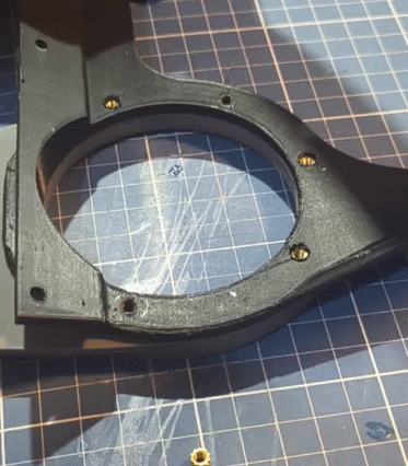
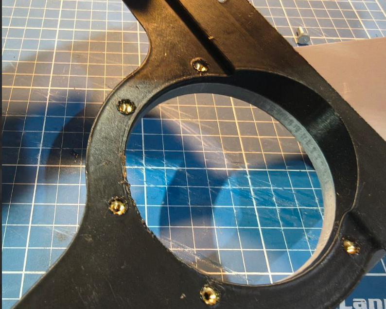
Now get your heatsets and your soldering iron and the heatsets. Warm it up to 300ºC if you're using PETG or ASA, 250ºC for PLA.
Front frame
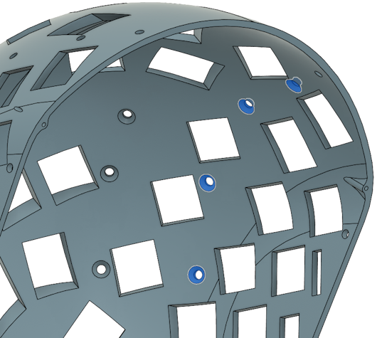
There are 6 holes that those inserts should be placed
Front frame
First, place the helmet facing the side, make sure its stable. Then put one of the heatsets with the thin part facing the hole. Put the soldering iron tip on the top of the heatset and wait a few seconds until it starts melting the plastic and going trough the plastic. Try to do this slowly without pushing too hard. Use as little force as possible and try to avoid pushing it past the surface. Try to keep the soldering iron as straight as possible relative to the surface.
Front frame
Once all 6 are installed, you finished it! Now if you going to need the extender, lets do the same for it.
Front frame
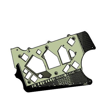
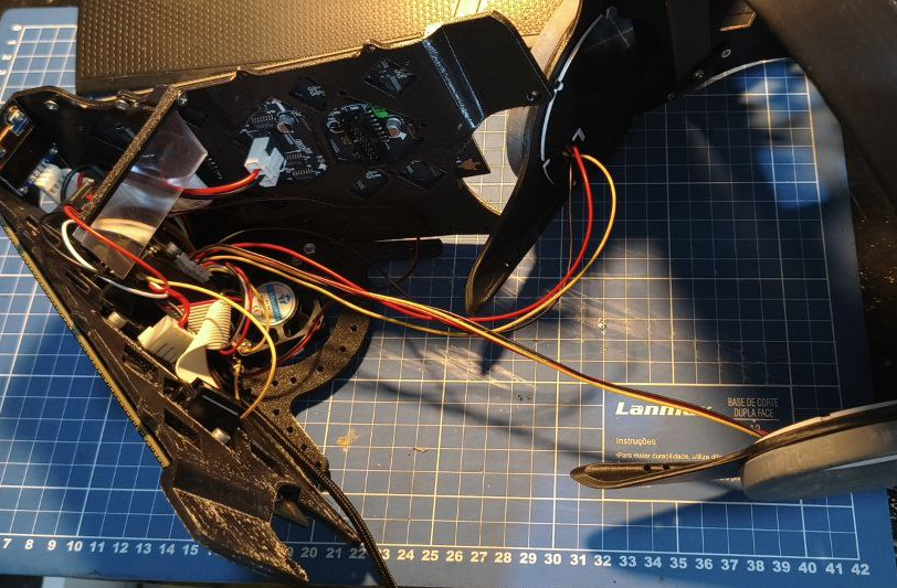
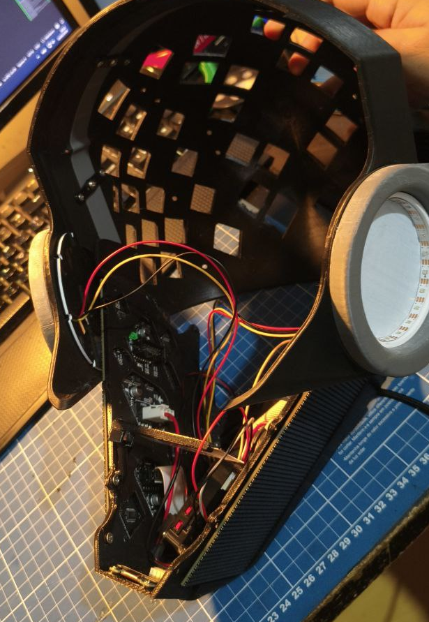
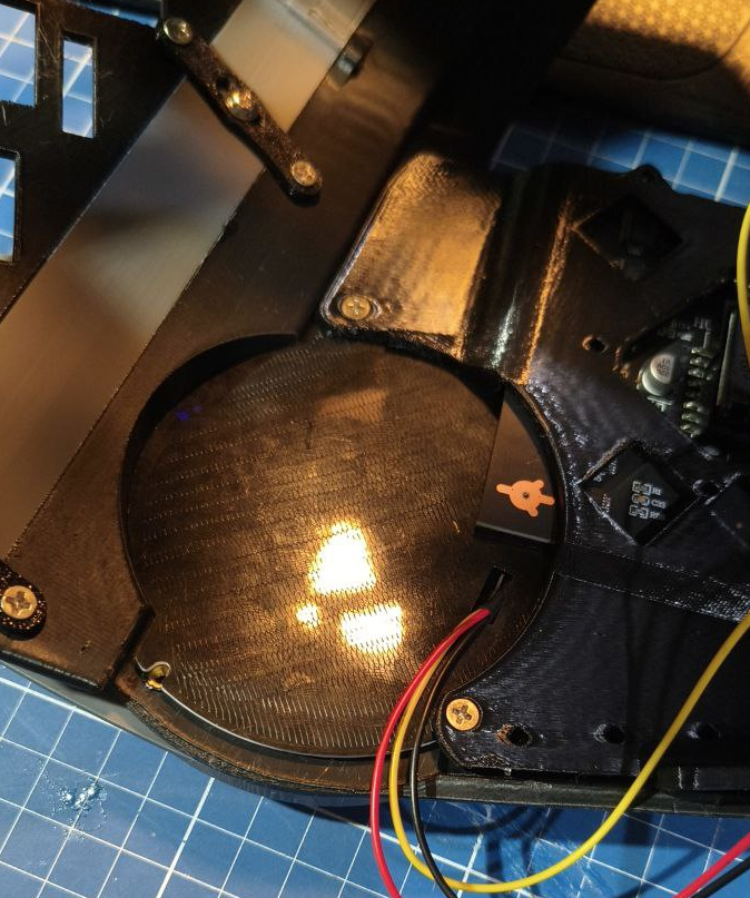
The front frame is where all the electronics usually go. At this point, i dont have spare parts to record a footage of the whole assemble process. So I'll show just the printing process for now.
Load the model and place it flat on the print bed
Led holder
Upon clicking "Slice" you'll notice that some supports appear
front frame
Most of those supports aren't necessary, so we're gonna right click and add a cube support blocker.
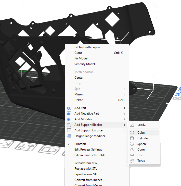
front frame
Scale it and move to be it like this, covering the whole front frame except the back of it.
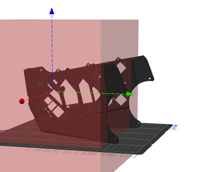
front frame
Now slice and you will notice only two supports appear
front frame
Thats it. Print it like that.
The front frame is where all the electronics usually go. At this point, i dont have spare parts to record a footage of the whole assemble process. So I'll show just the printing process for now.
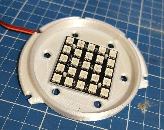
Its recommenmded to have a multicolor 3d printer here. Its possible to do it without one too but the results might not come as good. This section will require a bit of soldering and electronics. You can totally use the original MK16 led holders if you want, this guide only exists because the way I made the holders, feels to me that they come out better.
You can also swap the ws2812b led strip with a single color led too. I'm using ws2812b because they're RGB.
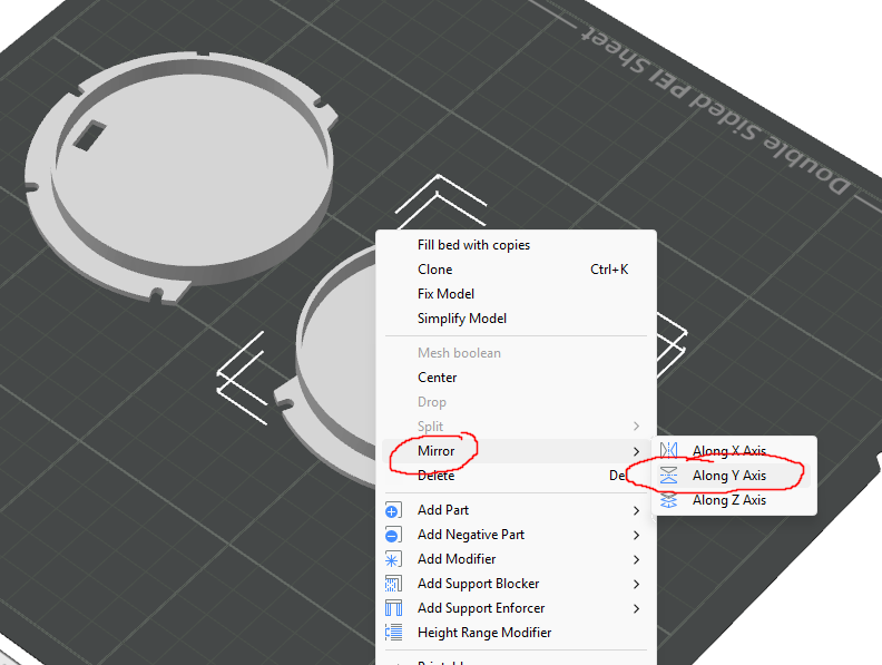
Firstly you will load the model and then place flat on the print bed
Then click on the model, press Ctrl+C and then Ctrl+V to create a copy.
Right click one of them and selec mirror and then mirror Y
Led holder
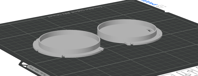
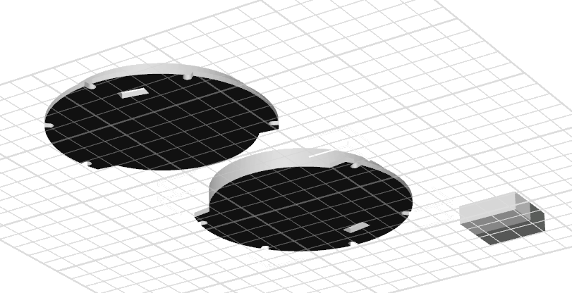
Then they should look like this on the print bed
Led holder
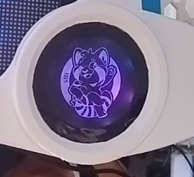
Make them all white. If you get some silver PLA or other color that reflects light better than white, use it instead.
Now, if you have a multicolor print, make the first layer back. If you dont have a multicolor print, you can use black PLA, and then pause the print mid print and swap the filament.
Led holder
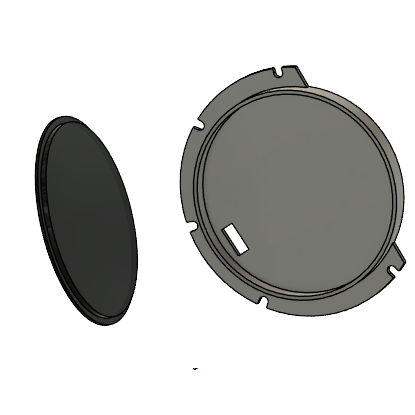
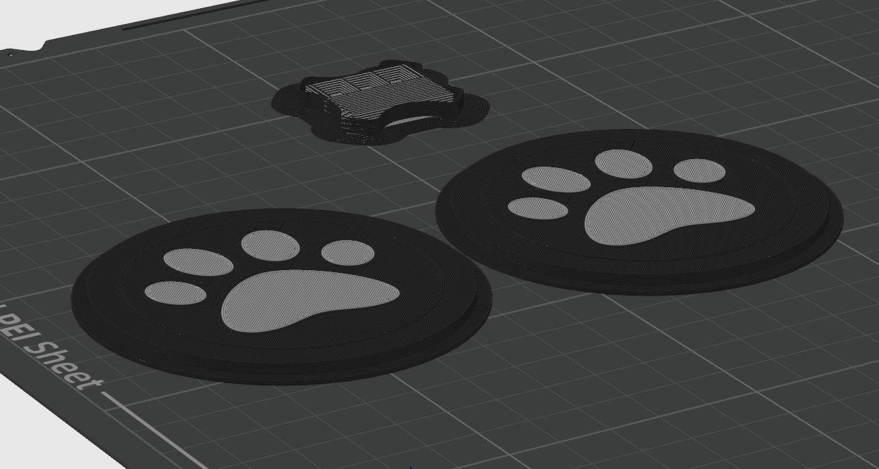
Now come a tricky part. If you dont have a multicolor print, you an either lasercut a piece of acrylic in to a circle and fit on the model. Or you can print a circle using transparent PLA and fit in the circle. Using a smooth PEI sheet here is important. You can go with a texturized one, but you will need to enable ironing and print it upside down and enable supports.
Led holder
Upon importing the model it will be a solid piece.
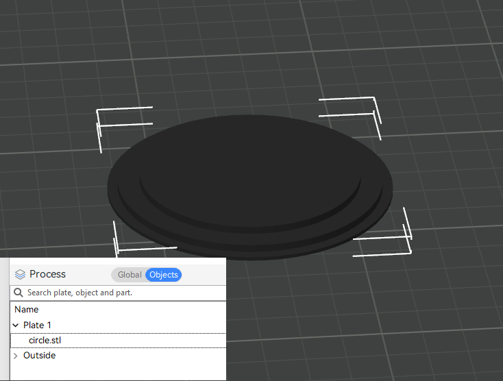
Led holder
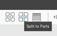
Then you need to click on the "split into objects" button
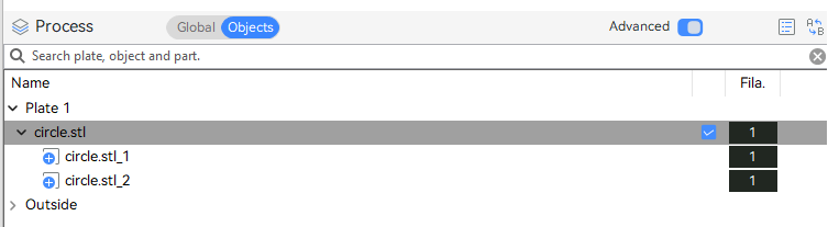
split into parts
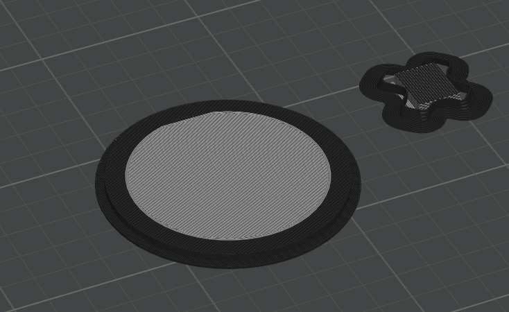
That way the object will become two. The inner circle and the outer.
Led holder
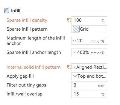
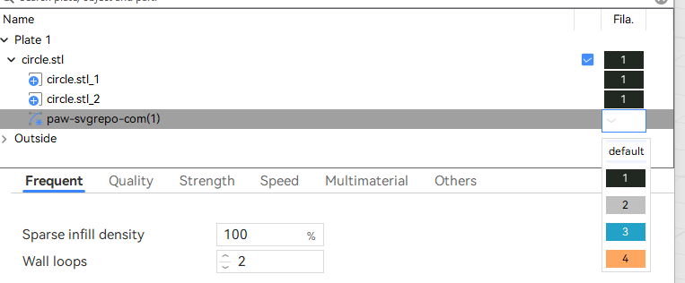
Just change the filament of one of the circle to be the transparent one. Remmber to change the infill to 100% and the infill pattern to be aligned and rectilinear
Led holder
Led holder
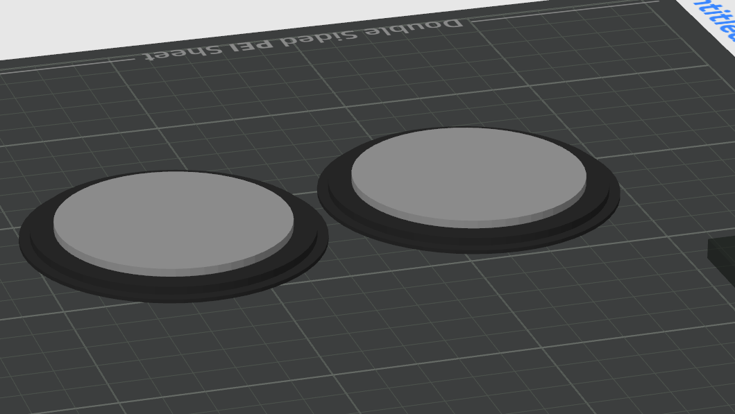
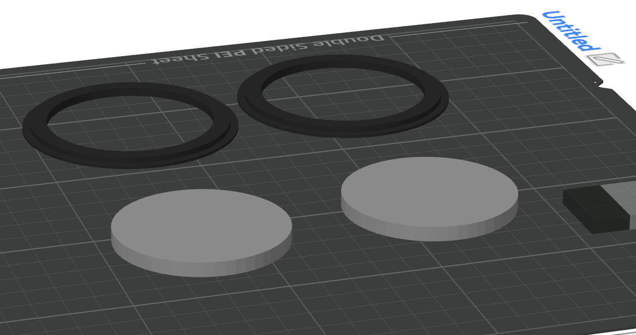
Then move them aparta, disable the rings and print the inner circles first then print the circles later in black PLA
Led holder
Alternativelly, you can lasercut a 57.7mm circle in acrylic.
Led holder
Then you need to print a black sticker with white or transparent background and glue over it.
Led holder
First import the model facing down. Keep it all balck!
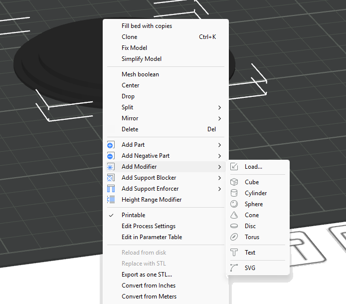
For the logo, get an SVG of your logo, you can use this site which has a bunch of SVGS. Select a SVG, download it, make the whole model black then right click on the model and select "Add modifier" and select an SVG
Led holder
Adjust the SVG size and position to be on the middle of the model. Also make sure it is thick enough to go trough the model
Led holder
If by any reason the model goes up and keep floating, select it and right click then select "Drop". Now in the object selection, change the filament of the SVG to the transparent one.
Led holder
It should look like this when sliced
Led holder
But wait, its not finished. We need t he light to go trough it... And if you notice, that part that supposed to be transparent is now black!
Led holder
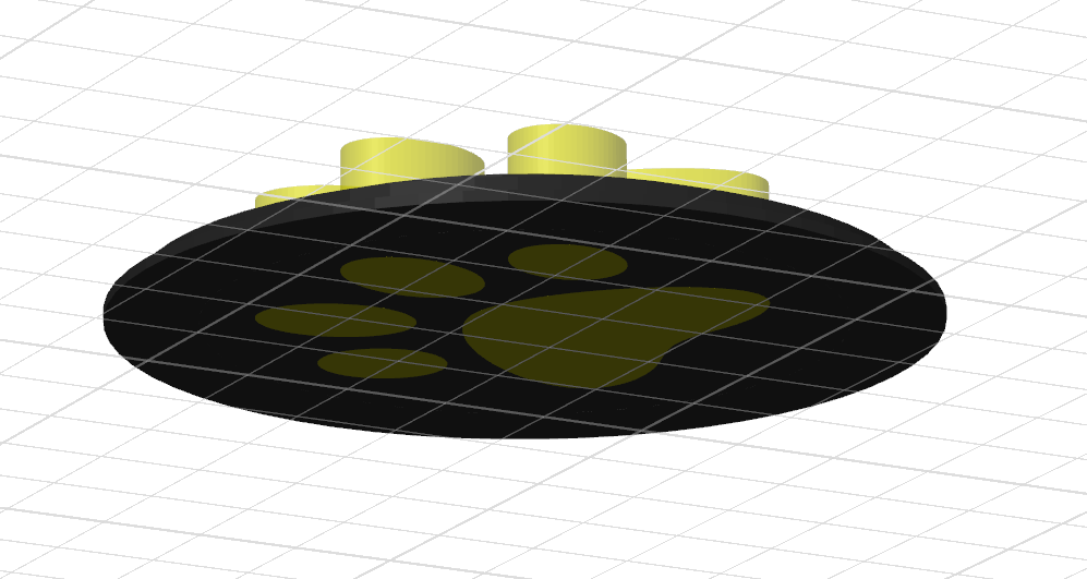
So we need to add a cube modifier to make it transparent again. Same process of the SVG but for a cube. Try to position it right above the second surface. Like this:
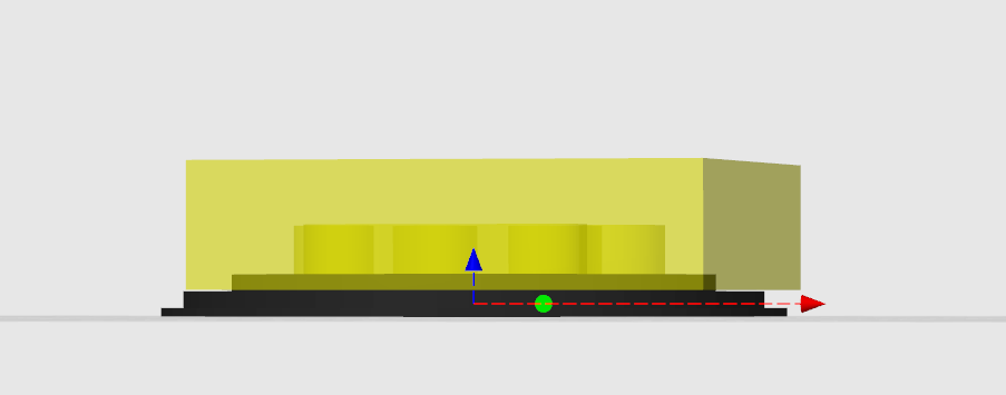
Led holder
This will make the top surface to look like this:
Led holder
While the bottom surface looking like this:
Led holder
Print two of them! Remmeber that you might need to flip one of the circles.
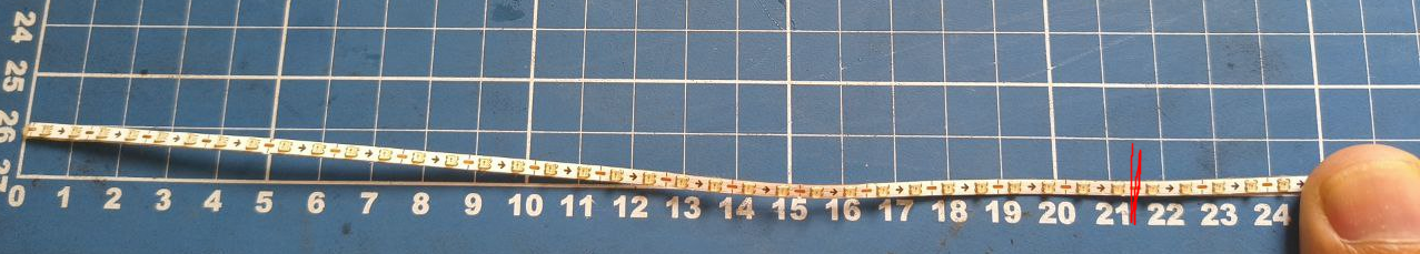
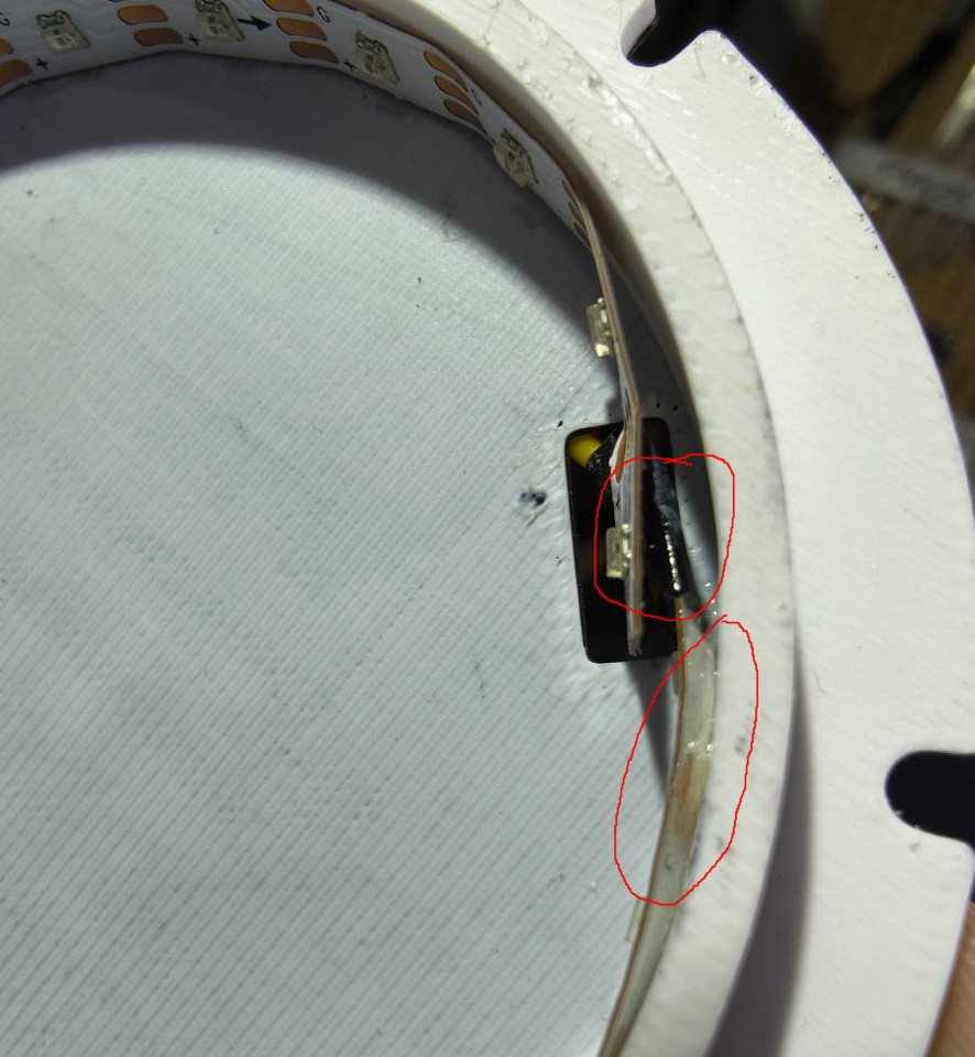
First, make sure you got the right led strip. Usually led strips are 12mm wide. We're looking for the ones with 2.7mm up to 5mm.
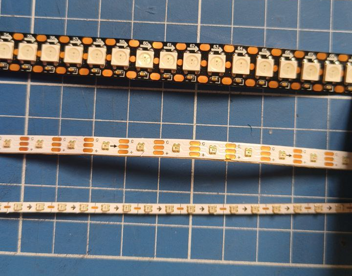
Led holder
Once you get the correct one, cut them in to two strips of 21~22cm.
Led holder
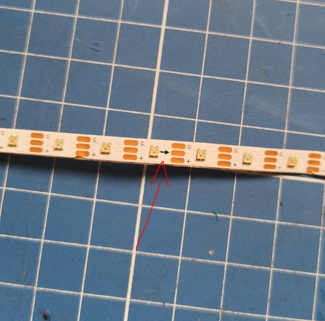
Now lets solder the terminals of the strip. Make sure to solder them in the correct orientation. Those adderessable led strips have an arrow indicating the direction
Led holder
Once you solder, remember to put somee heatshrink tube to cover the contacts, or later cover it with electrical tape or hotglue
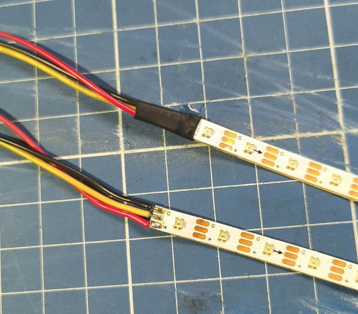
Led holder
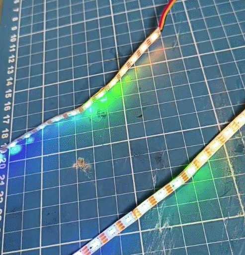
Make sure to test to see if they're working. I'm testing using a protopanda, but you can upload an FastLed sketch to an arduino board.
led holder
Under those trips, there is an adehesive tape, remove the cover
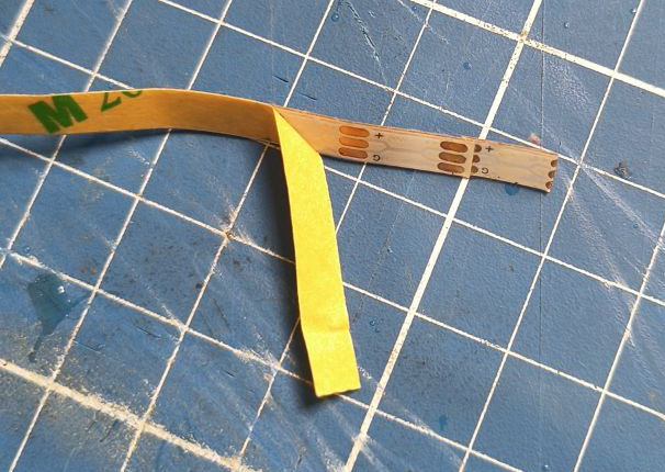
Led holder
And wrap around the inner edges of the led holder
Led holder
If you want, you can apply a bit of superglue on the end and the begin of the strip to keep them in place
Led holder
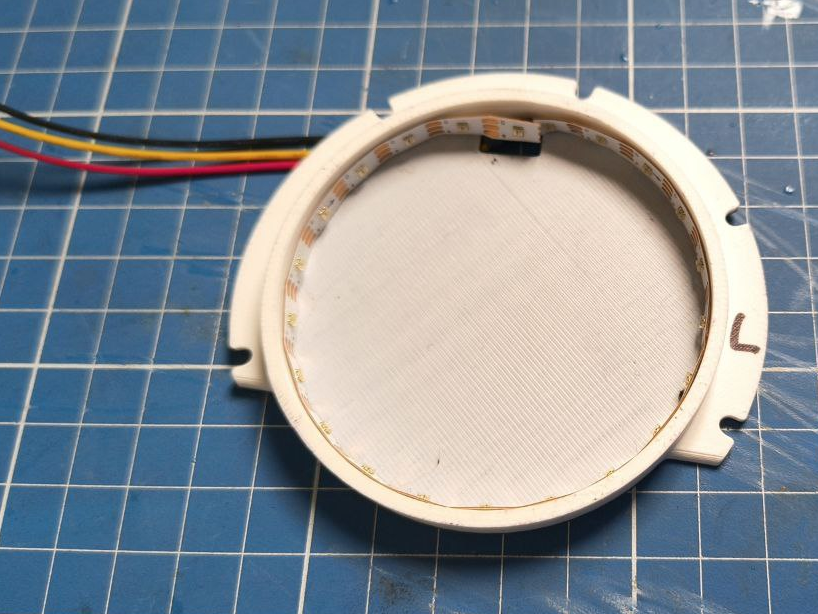
The back should look like this: (important, ideally, keep the wire going down on each side, would be easier to organize later)
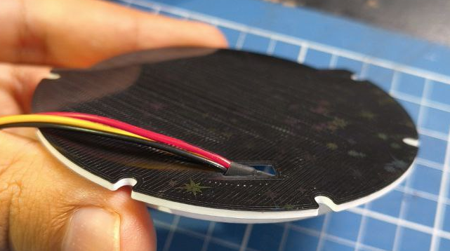
Led holder
Now cover with the cover!
Led holder
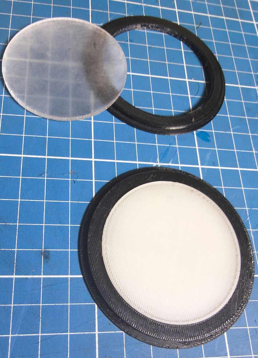
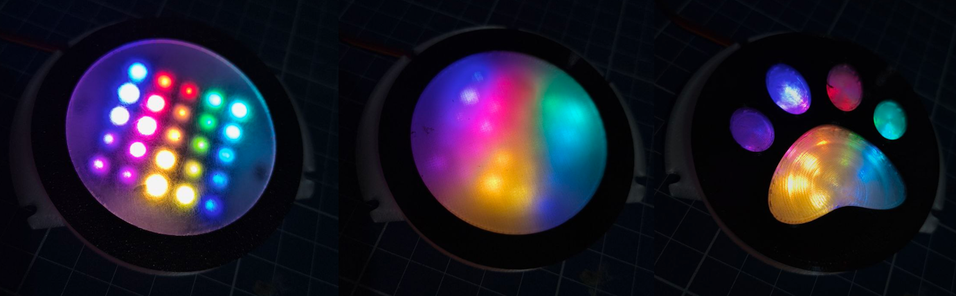
Now you should choose which is better for you. Top one is acrylic, bottom one is 100% infill clear PLA
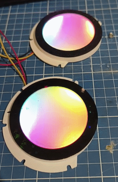
led
Or the custom logo thing

led
Alternatively, you can try using a 5x5 matrixes. But the leds will be visible.
Led holder
Altough the results aren't that good in person. You can clearly see the individual leds.
Led holder
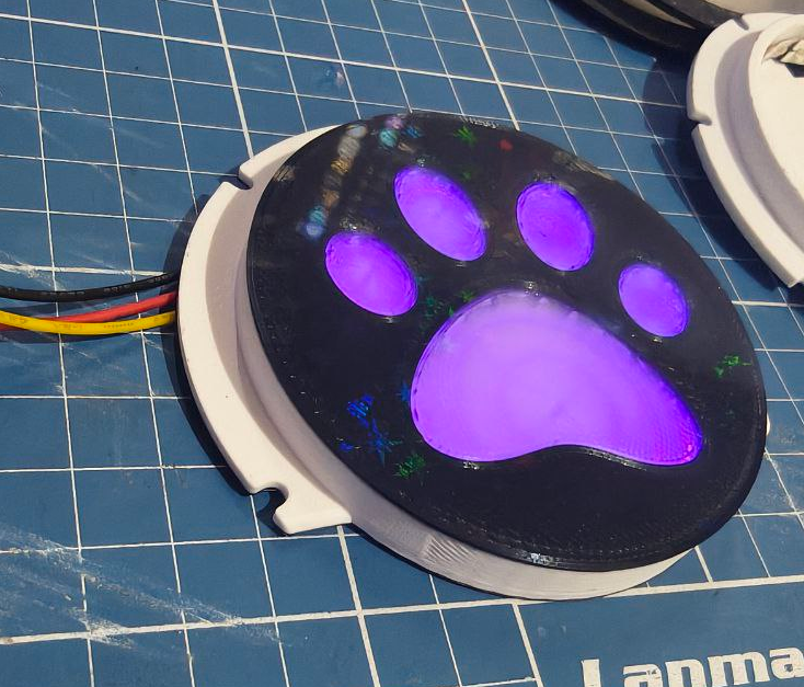
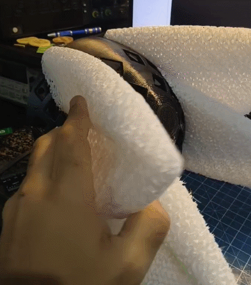
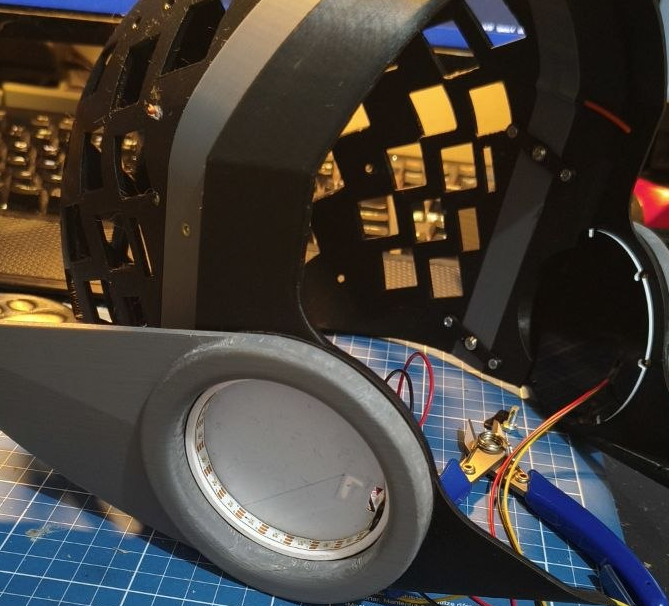
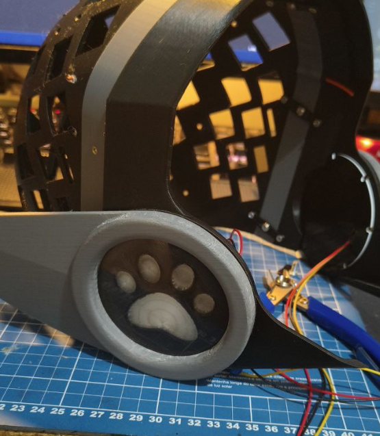
Once you decide which one you using, you can use just a bit of super glue. But DONT DO IT NOW!! You will need to align it once you finish assembling all parts. Dont use too much because they already fit snug in to the fin hole. And if you ever need to replace the led strip, you can easily open it
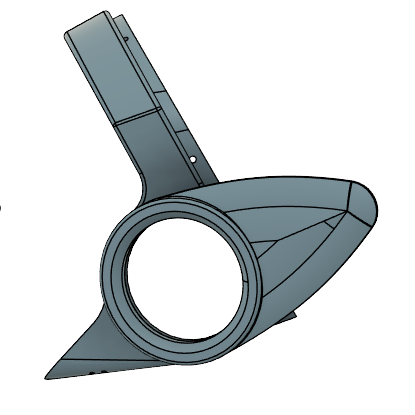
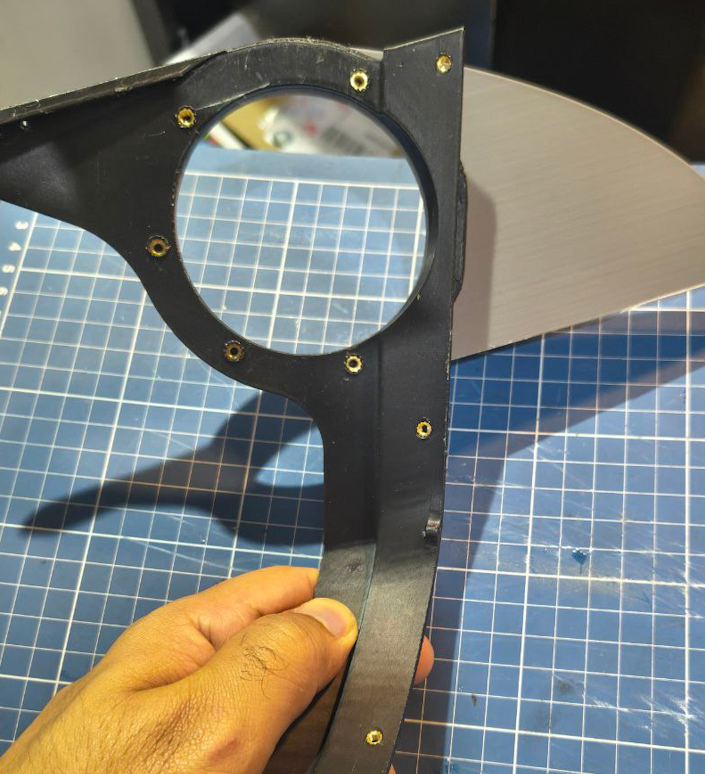
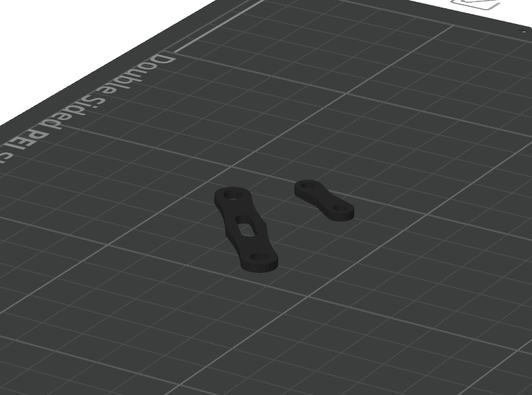
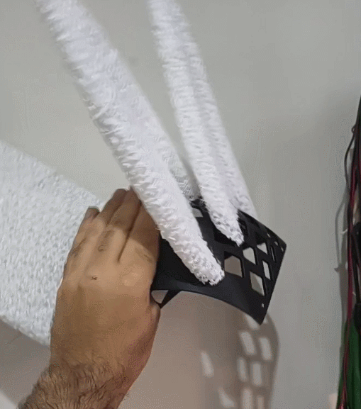
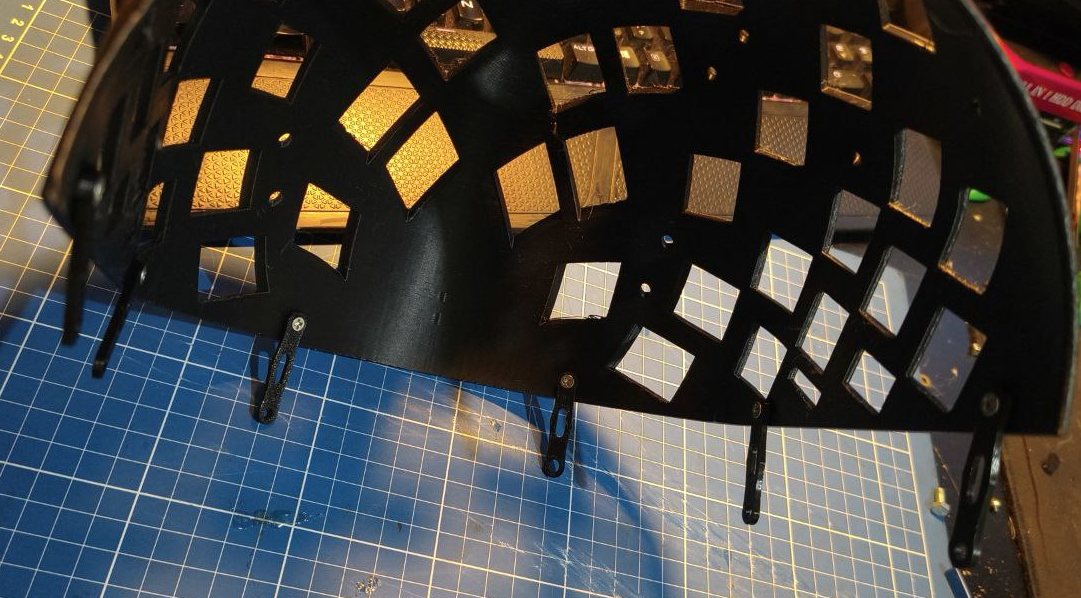
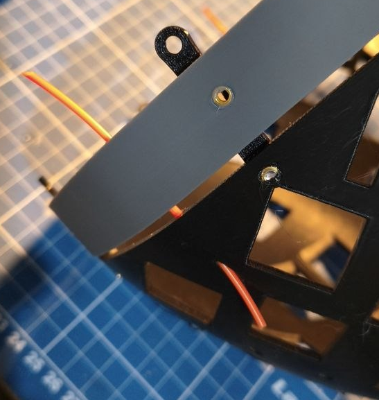
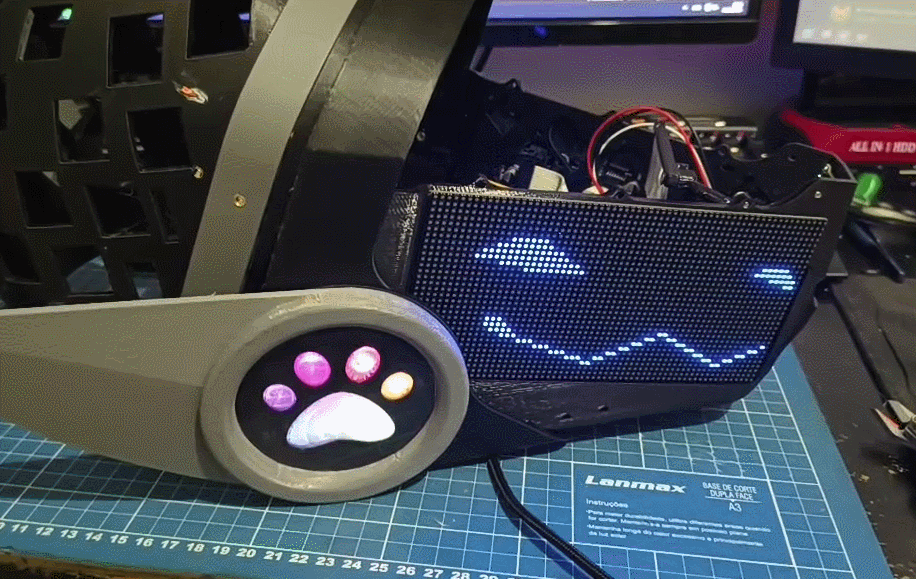
Clips are used to join together the back of the head with the headphones without the need to glue it. You can glue them too, but using screws might be stronger.
Yeah, you heard that right. PETG or ASA. DO NOT ATTEMPT TO PRINT THIS IN PLA. It WILL crack eventually. Its reccomended to print 8 of each. The small one is used in case your head fits perfectly on the model. If it needs extra space, print the extender and use the big clips.
Once you load the model, first click on lay flat
Fins
And place each of them facing down on the print bed. It should look like this:
clip
Then, clone each of those parts until you have at least 8 of each
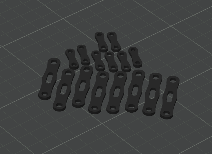
clip
They should join the back of the head, extender and the headphones together. For assembly guide, check the Assembling all parts together section.
The model support 2 and 4 ears. You can choose to print just two of them or all four of them. Or completely skip this section and make your own ears later. The ears will be printed in TPU. You can print them in PLA or PETG but they might end up too heavy or breaking easily since you wont be able to bend them.
ears
Disclaimer: Printing with TPU is annoying and some printers can't handle it well. In this guide I tried to guide each step with as much detail as possible. But printing with TPU has some hard parts. So i'd say, get used to printing in TPU before attempting this section.
They're printed using TPU so its flexible and ultra durable
ears
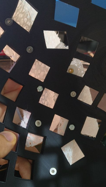
You will see the ears are split in to parts. Thats because they're too big and dont fit on the printer.
ears
The requirement is is changing the infill to 10%, removing walls and top shell layers. And add a few modifier cylinders on those holes. They should have 3 walls, those are the places where the heatsets will stay.
ears
When sliced, it should look like like this.
ears
You can fit two ears at the same time (REMEBER TO FLIP THEM). When you finish, abuse the super glue to put the two parts together.
once they're printed, heat your soldering iron on about 300~350ºC with a m4 tip and put all four of the heatsets. They will go on the back of the head with the m4 scews.
ears
First position four M4 crews in the holes, push or screw them in the holes until they start poking on the other side
ealls
all
Then position the left ear with the topmost screw, start rotating the screw so it gets closer. Then align the ear with the bottom one. Do this for all screws
eallars
Do this for all four ears.
BUT MOCK, I DONT WANNA USE SCREWS, CAN I USE THE OLD FASHION WAY AND GLUE?
yeah.
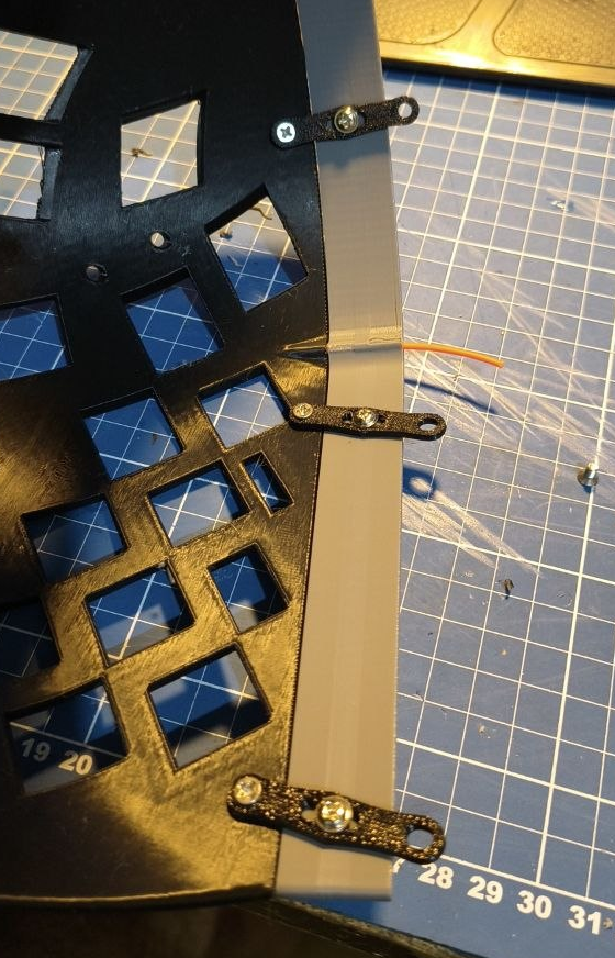
But I'll show with screws! The idea is you use the clips to attach the back with the headphones. I'll show how to do it with the extender, if you end up not needing it, use the smaller clips instead. Get 6 clips and 6 M3 6mm screws. Screw the clips in place with just enough pressure so they stay in place but can be rotated if you push them.
all
Now slide in the extender (if not using the extender, use the small clips and do the headphones now.), you'll notice the alignment might be a little tricky. Thats why there is a aligment hole.
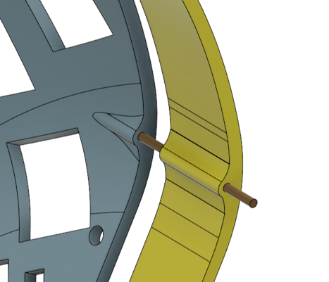
all
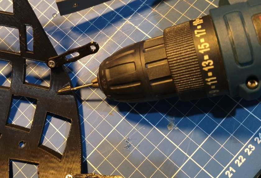
The idea there is you use a piece of filament or some other thing to keep the parts in place. If the hole end up beeing too small due, you can drill it with a 1.7mm drill.
all
Here I'm using piece of PLA filament to align.
all
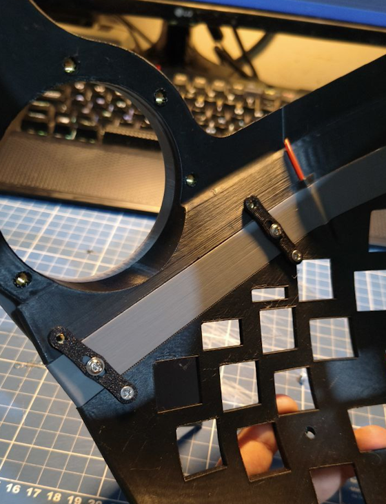
Now place all the screws in the extender and tighten all screws. Dont tight too hard though.
all
Now just slide in the headphones. With the alinment holes it will be in place, ready to screw.
all
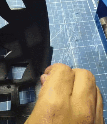
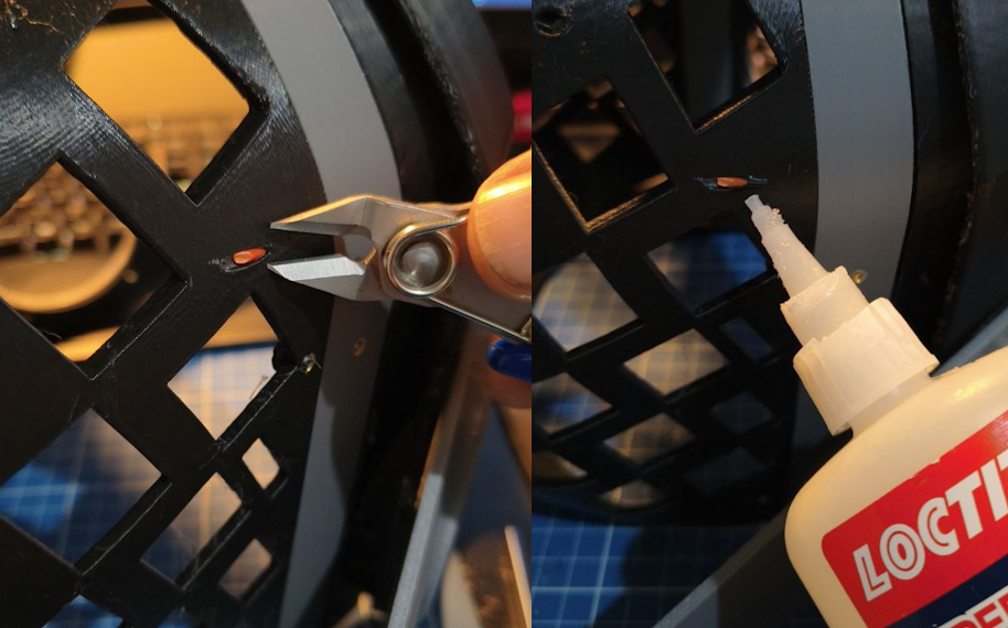
Once everrything is secured with screws, you can put a pinch of glue on the filament strand at the back of the head and then cut it with a straight cutting plier.
all
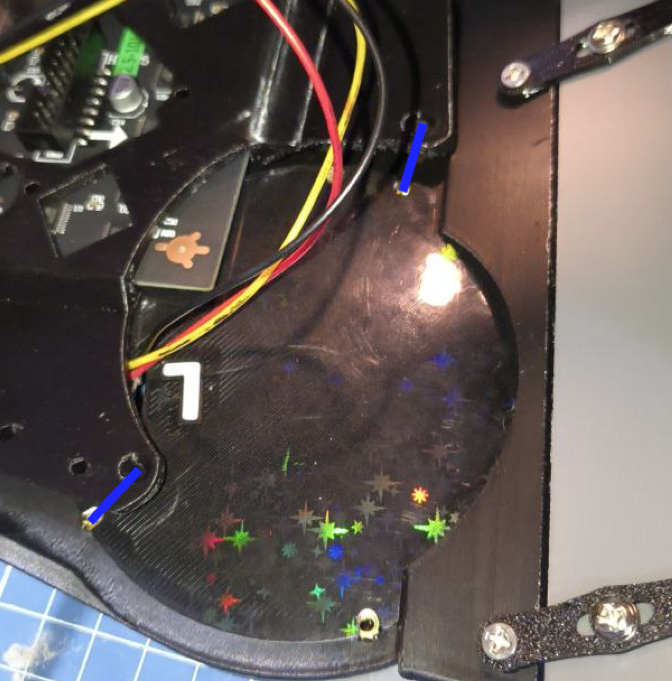
Check which side each of the side led holders goes.
Then simply push it until it latches. You can use a m3 screw to keep it in place for now. The front frame will hold it there.
all
Now take your time to align the cover. If you're not going to sand anything else or apply paint, you can glue it now. Otherwise, save the gluing to be the last step before calling it finished.
all
We're almost there!
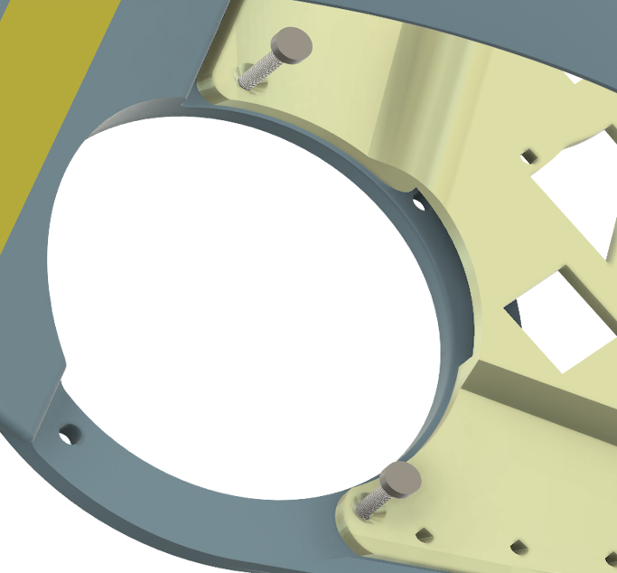
First, you will need to position the two parts, and then slide the front frame, either by the bottom or the top by gently bending the back of the front frame.
all
all
Now you'll have to align those two holes
all
Use the M3 10mm screws to fix it in place
all
Screw it tight, but not too much to dont damage any parts.
all
AND THERE YOU HAVE IT! Done!
all